
DC Motor Speed Controller Circuit

The motor speed controller is designed around the LM1014 integrated circuit, which is a versatile operational amplifier. This IC is employed to create a feedback loop that adjusts the voltage supplied to the DC motor, thereby controlling its speed. The circuit configuration typically includes a potentiometer, which allows for manual adjustment of the reference voltage, enabling the user to set the desired speed of the motor.
The controller operates by monitoring the current flowing through the motor. As the load on the motor increases, the current rises, which is sensed by the LM1014. This increase in current is fed back to the input of the operational amplifier, which adjusts the output voltage accordingly to maintain the desired speed. The output stage of the LM1014 may be coupled with a transistor or a MOSFET to handle the higher current requirements of the motor, ensuring efficient operation.
Additional components in the circuit may include diodes for flyback protection, capacitors for filtering, and resistors for setting gain and stability. The design must ensure that the LM1014 operates within its specified voltage and current limits to prevent damage. Proper layout and thermal management are also critical, as the LM1014 and associated power components may generate heat during operation.
In summary, the motor speed controller based on the LM1014 provides an effective means of regulating the speed of a DC motor by utilizing feedback from motor current, allowing for precise control suited to various applications.This motor speed controller uses a single IC LM1014 to control the speed of a DC motor. It senses the increase in the motor-current when the rotation of th.. 🔗 External reference
Related Circuits
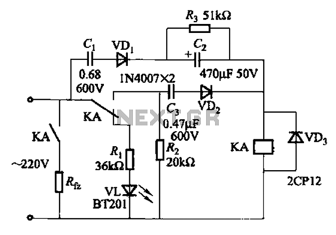
The AC power supply voltage is normal, and a relay is connected to the load (Rfz) circuit. In the event of a load short-circuit failure, the voltage across relay KA drops rapidly, causing KA to release and disconnect the...
The following circuit illustrates a fully linear diode sensor circuit diagram. This circuit is based on the A748 integrated circuit (IC). Features include the use of an operational amplifier (op-amp). The fully linear diode sensor circuit utilizes the A748 IC...
The output level was set to 3.8V peak to peak. The initial objective was to compare several different operational amplifiers (op-amps) before further optimizing the circuit. The op-amps evaluated were the TL072, LM4562, and OPA2134. The distortion spectra are...
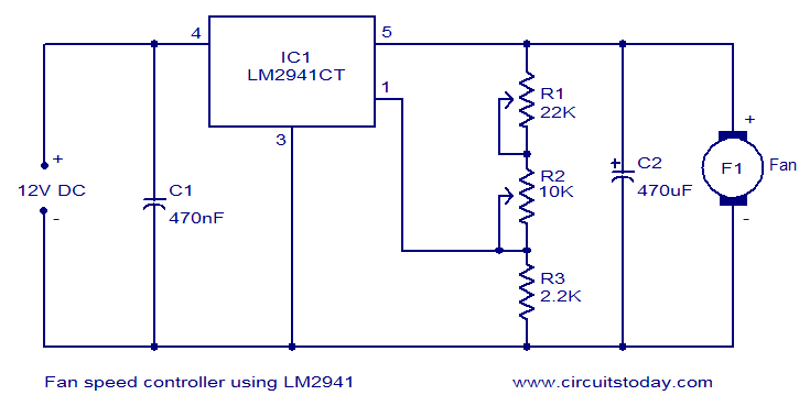
Numerous electronic circuits designed for fan speed control have been documented, and this one presents an alternative method. The circuit diagram illustrates a 12V DC fan speed controller utilizing the LM2941CT integrated circuit, which is a low dropout 1A...
This design circuit is for a mass air flow (MAF) sensor. The MAF sensor converts the volume of air entering the engine into a voltage signal. The main components of the MAF sensor include a thermistor, a platinum hot...
The BTS412B functions as two high-side power MOSFET switches, while the BU271L components rated for 50V serve as the low-side switches. Together, these elements can form a bi-directional H-bridge DC motor drive circuit, as depicted in Figure 11-1l. This...