
Philips Amplifier 200w Circuit

The described circuit is a high-power switching regulator designed for efficient power conversion, typically used in applications requiring substantial power output. The PHP1BN11QT is a high-performance power MOSFET that provides efficient switching capabilities, reducing power losses during operation.
The circuit layout should include two PHP1BN11QT transistors configured in a complementary push-pull arrangement to maximize output power. The input stage of the circuit must handle voltages between 30V and 45V DC, which necessitates robust voltage regulation and filtering components to ensure stable operation under varying load conditions.
To achieve the desired performance, careful consideration must be given to the gate drive circuitry for the MOSFETs. A dedicated driver circuit may be employed to ensure rapid switching and minimize transition losses. Additionally, the design should incorporate adequate heat sinking for the MOSFETs to manage thermal dissipation, as high power outputs can lead to significant heat generation.
Output filtering is also essential to smooth the output voltage and reduce ripple, which can be achieved using a combination of inductors and capacitors. The selection of these components should be based on the desired output characteristics and the load requirements.
Overall, the circuit must be designed with attention to detail regarding component ratings, layout considerations, and thermal management to ensure reliable and efficient operation at the specified power output.This circuit possible to deliver about 200W power output produce by Phillips Semiconductor. Using 2 PHP1BN11QT, input voltage between 30 and 45 VoltsDC for this. [read more] 🔗 External reference
Related Circuits
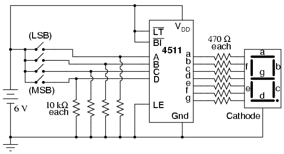
Digital circuits are circuits that handle signals restricted to binary states of zero and a maximum value. This is in contrast to analog circuits, where signals can vary continuously within the limits set by power supply voltage and circuit...

This is a high-fidelity, high-quality audio amplifier circuit diagram. A pre-amplifier is not required. Component list: R1, R4 = 47K 1/4W resistors; R2 = 4.7K 1/4W resistor; R3 = 1.5K 1/4W resistor; R5 = 390Ω 1/4W resistor; R6 =...
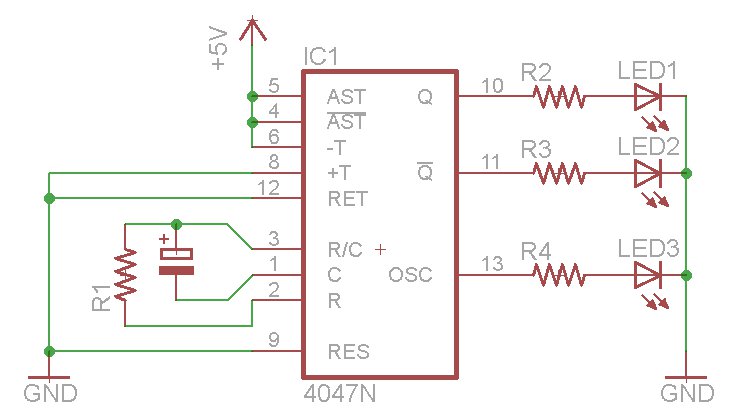
The oscillator output generates a signal that is approximately twice the frequency of Q. The other pins will be considered subsequently. In a brief video demonstration, LEDs are connected to all three outputs, illustrating the alternating behavior of Q...
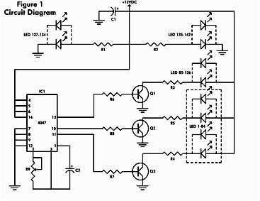
It consists of a 4047 low-power monostable/astable multivibrator, IC1, used in the astable mode to provide the timing pulses to control the flash rate of the LEDs. To accomplish the astable mode, pins 4, 5, 6, and 14 are...
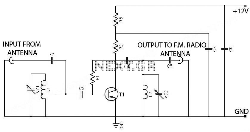
FM Booster, Active FM Antenna Amplifier. This FM booster can be used to listen to programs from distant FM stations clearly. The circuit comprises a common-emitter tuned RF preamplifier wired around VHF/UHF transistor 2SC2570. The FM booster circuit is designed...
A circuit is being designed to trigger solenoid valves for airbags in a car, requiring a time range of 0 to 1 second. The selected valves operate at 12V, 0.5A, and can activate within a maximum speed of 200...