
12V DC Light Dimmer Circuit Using 555 Timer IC

The described circuit utilizes a combination of resistors, a potentiometer, a capacitor, and a diode to control the brightness of a lamp. The operation of the circuit is contingent upon the position of the potentiometer, which acts as a variable resistor, allowing for adjustments in the charging and discharging rates of the capacitor.
In the upper position of the potentiometer, the circuit configuration allows for a rapid charge of the capacitor. The two 1k resistors are arranged in series with the capacitor and the diode, which permits current flow in one direction only. This configuration results in a quick accumulation of voltage across the capacitor, leading to a brief positive interval. The subsequent longer negative interval occurs as the capacitor discharges, causing the lamp to dim significantly.
In contrast, when the potentiometer is adjusted to the lower position, the capacitor's charging path includes the 50k potentiometer in series with the two 1k resistors. This higher resistance results in a slower charge time for the capacitor. The discharge path through the lower 1k resistor allows for a quicker release of stored energy. Consequently, this configuration produces a longer positive interval where the lamp remains bright and a shorter negative interval during the discharge phase.
The overall design of the circuit exemplifies the principles of RC (resistor-capacitor) timing circuits, where the time constant is influenced by the resistance and capacitance values. The behavior of the lamp, transitioning between dim and bright states, is a direct result of the varying charge and discharge cycles dictated by the potentiometer's position. This circuit can be effectively used in applications requiring adjustable lighting conditions, such as in dimmers for lamps or other lighting systems.When the potentiometer is at the up position, the capacitor will charge quickly through both 1k resistors and the diode, producing a short positive interval and long negative interval which dims the lamp to near darkness. When the potentiometer is at the lower position, the capacitor will charge through both 1k resistors and the 50k potentiometer
and discharge through the lower 1k resistor, producing a long positive interval and short negative interval which brightens the lamp to near full intensity. 🔗 External reference
Related Circuits
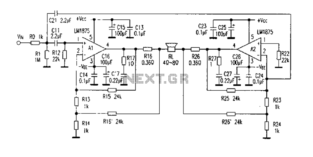
The DC current negative feedback BTL circuit illustrated in Figure 2 eliminates the standard BTL circuit capacitors C12 and C22, which affects the DC characteristics of the circuit. Resistors R16 and R26 function as sampling resistors, while R15, R16,...
A teleremote circuit enables the switching on and off of appliances through telephone lines. It can be used to control appliances from any distance, overcoming the limited range of infrared and radio remote controls. The circuit can switch up...
The first half of the circuit (IC1a) features an input sensitivity of 3 mV and includes a frequency correction network consisting of capacitors C5, C3, and resistors R6 and R8. The bass signal from the phono input is amplified,...
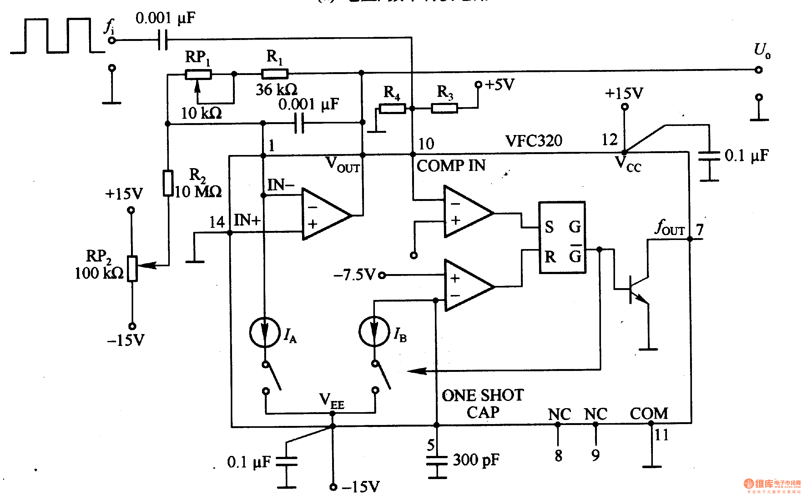
Figure 1-22 (a) illustrates a circuit that converts an input voltage of 0 to +10V (Ui) into a pulse with an output frequency ranging from 0 to 100kHz. In this configuration, pin 7 of the VFC320 is connected to...
This is a very simple project using a printed circuit board and 8 components. It will flash an ordinary 3mm or 5mm (1/8" or 1/4") LED at a rate of about one flash per second. This circuit works on...
The crystal radio derives its name from the galena crystal (lead sulfide) utilized for rectifying signals. A "cat's whisker" wire contact was adjusted on the crystal's surface until a diode junction was established. The 1N34A germanium diode serves as...