
12V Fan Directly on 220V AC

In this circuit, the design employs a capacitive voltage divider as the primary method for power supply, which is particularly advantageous in compact applications. The arrangement begins with the connection to the mains voltage, where the capacitive divider is formed by capacitor C1. This capacitor must be selected carefully to ensure it can handle the peak voltage levels without failure. The resistors R1 and R2 serve a dual purpose: they limit the initial surge current when the circuit is powered on and help protect the circuit from potential overcurrent situations.
The use of discharge resistors R3 and R4 is crucial for ensuring safety by discharging capacitor C1 when the circuit is turned off. This prevents the risk of electric shock from residual voltage at the plug. The zener diode D1 acts as a voltage clamp, ensuring that the output voltage remains within safe limits, even under varying load conditions. This diode's specification should be chosen based on the expected maximum output voltage and power dissipation.
When calculating the value of capacitor C1, it is important to consider the capacitive reactance at the operating frequency (50 Hz). The formula for calculating the required capacitance based on the desired output current is essential to ensure the circuit operates within its intended parameters. The final choice of capacitor should also consider the physical dimensions and mounting options available in the application, which may necessitate the use of multiple smaller capacitors rather than a single larger one.
Overall, this circuit design illustrates a practical approach to providing power to small fans in situations where space is limited and safety requirements must be strictly adhered to. The choice of components and their arrangement within the circuit are critical for ensuring reliable operation and compliance with electrical safety standards.This circuit idea is certainly not new, but when it comes to making a trade-of between using a small, short-circuit proof transformer or a capacitive voltage divider (directly from 230 V mains voltage) as the power supply for a fan, it can come in very handy. If forced cooling is an afterthought and the available options are limited then perhaps t here is no other choice. At low currents a capacitive divider requires less space than a small, short-circuit proof transformer. R1 and R2 are added to limit the inrush current into power supply capacitor C2 when switching on. Because the maximum rated operating voltage of resistors on hand is often not known, we choose to have two resistors for the current limit.
The same is true for the discharge resistors R3 and R4 for C1. If the circuit is connected to a mains plug then it is not allowed that a dangerous voltage remains on the plug, hence R3 and R4. Capacitor C1 determines the maximum current that can be supplied. Above that maximum the power supply acts as a current source. If the current is less then zener diode D1 limits the maximum voltage and dissipates the remainder of the power.
It is best to choose the value of C1 based in the maximum expected current. As a rule of thumb, start with the mains voltage - when calculating C1. The 12 V output voltage, the diode forward voltage drops in B1 and the voltage drop across R1 and R2 can be neglected for simplicity. The calculated value is then rounded to the nearest E-12 value. The impedance of the capacitor at 50 Hz is 1 / (2p50C). If, for example, we want to be able to supply 50 mA, then the required impedance is 4600 (230 V/50 mA).
The value for the capacitor is then 692 nF. This then becomes 680 nF when rounded. To compensate for mains voltage variations and the neglected voltage drops you could potentially choose the next higher E-12 value. You could also create the required capacitance with two smaller capacitors. This could also be necessary depending on the shape of the available space. It is best to choose for C1 a type of capacitor that has been designed for mains voltage applications (an X2 type, for example).
🔗 External reference
Related Circuits
A LED is defined as "light-emitting diode: diode such that light emitted at a p-n junction is proportional to the bias current; color depends on the material used." As the LED is a diode, it doesn't conduct electricity in...
%2BCircuit%2Bdiagram%2Busing%2BCD4047%2Band%2BIRFZ44%2Bpower%2BMOSFET.png)
This simple low-power DC to AC inverter circuit converts 12V DC to either 230V or 110V AC. By making simple modifications, it is also possible to convert 6V DC to 230V AC or 110V AC. This inverter can be...
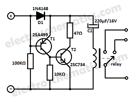
Protect your equipment with this compact 12V time delay relay circuit. The SMPS-based power supply of modern electronic devices is susceptible to voltage spikes. This 12V time delay relay circuit is designed to safeguard sensitive electronic devices by providing a...
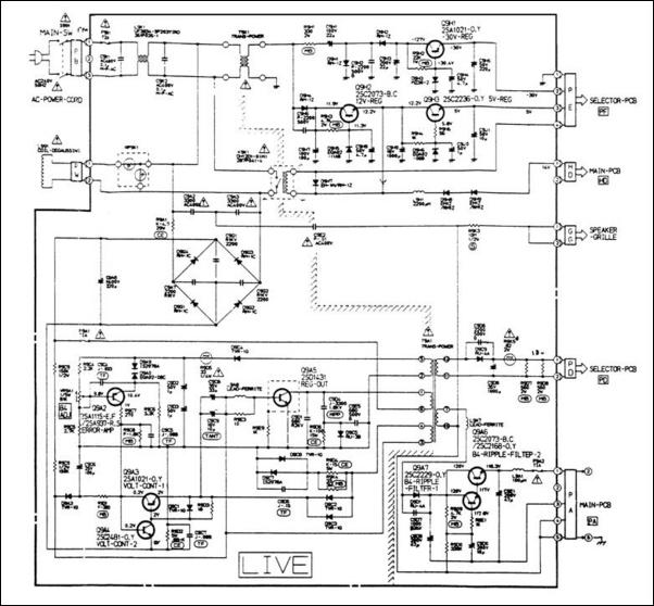
A 12V switching power supply schematic has been observed to generate significant heat, which has prompted discussions among users in prominent forums, such as dp. The 12V switching power supply is a crucial component in various electronic applications, providing...
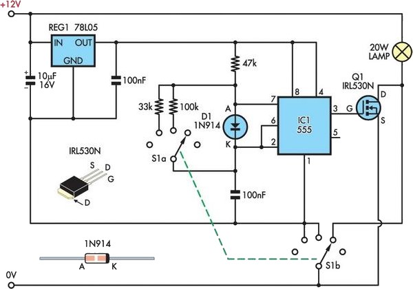
A 12V 20W halogen lamp (MR16) is utilized in a bike light system powered by a 4.2Ah SLA battery. Due to the limited battery life at this power rating, a cost-effective light dimmer has been designed to reduce battery...
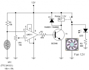
The circuit schematic diagram of a fan speed control system that activates only when necessary. When the transistor heats up, the fan will automatically turn on. The fan speed control circuit operates based on the temperature of the transistor, utilizing...