
12V Time Delay Relay Circuit

This 12V time delay relay circuit is designed to safeguard sensitive electronic devices by providing a delay before activating the connected load. It utilizes a relay to control the power supply to the device, ensuring that any transient voltage spikes are dissipated before the device is powered on.
The circuit typically includes a power supply section that converts the input voltage to the required 12V. This is often achieved using a switch-mode power supply (SMPS) which is efficient and compact, making it suitable for modern electronic applications. The relay is selected based on the load requirements, and it is crucial to ensure that it can handle the current and voltage specifications of the connected equipment.
A time delay feature is implemented using a timing circuit, which can be constructed with a resistor-capacitor (RC) network or a dedicated timer IC. When the circuit is powered on, the timing circuit begins to charge, and once it reaches a predetermined voltage level, it activates the relay. This delay allows for any initial power surges to settle, thus protecting the connected equipment from potential damage.
The circuit may also include additional components such as diodes for flyback protection, ensuring that voltage spikes generated by the relay coil do not affect the rest of the circuit. Capacitors may be added to filter out noise and stabilize the power supply.
In summary, this 12V time delay relay circuit is an effective solution for protecting sensitive electronic devices from voltage spikes, utilizing modern components and design techniques to ensure reliability and efficiency in operation.Protect your equipments with this tiny 12V time delay relay circuit. The SMPS based power supply of these modern electronic devices is vulnerable to spikes.. 🔗 External reference
Related Circuits
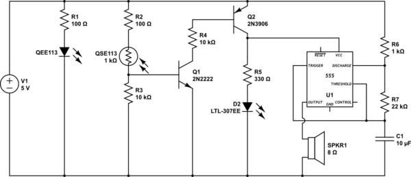
This circuit detects when a tube is empty and pulses a piezo buzzer at 5-second intervals. It is currently operational with a 5V supply on a breadboard but needs to be adapted for a 12V supply from a wall...

This design circuit is for a temperature sensor that utilizes an LM335 integrated circuit (IC) to convert ambient temperature into an equivalent output voltage. The output voltage of the LM335 increases by approximately 10 mV for every 1 degree...

It utilizes two LM358 operational amplifiers, A2 and Ar, to create a voltage measurement comparison control circuit for upper and lower limit voltage settings. The circuit includes a Raspberry Pi adjustment potentiometer (RPi) and an additional potentiometer (RP2) to...
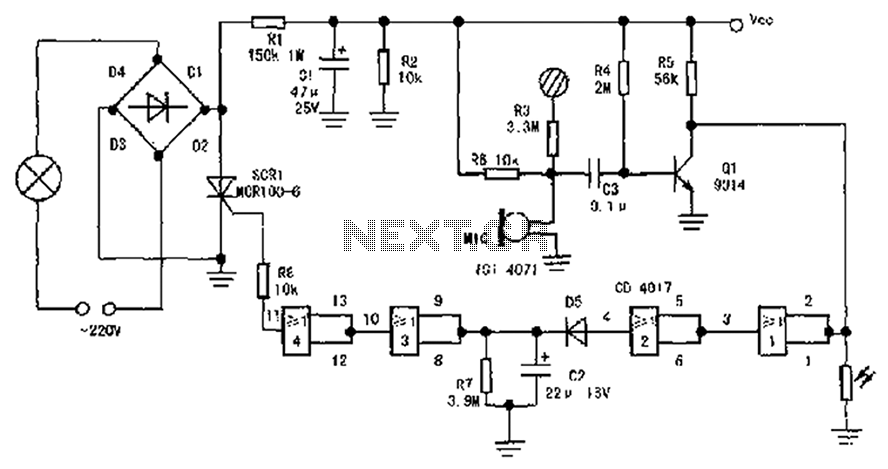
The circuit diagram illustrates a sound, light, and touch-controlled delay self-extinguishing switch. It comprises three main sections: the power circuit, the signal conversion detecting circuit, a delay circuit, and a control circuit. 1. Power Circuit: This section consists of...
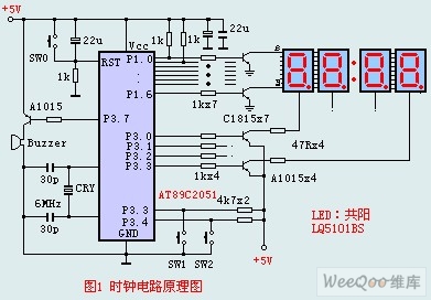
The circuit design incorporates an anodic Nixie tube for the LED display. It utilizes the LQ5101BS general luminous diode, with the driving transistor being either the 2SA1015 or 2SC1815 types, which are readily available. Additionally, low-power transistors such as...
This cost-effective circuit can be connected to an air conditioner, refrigerator, or any other advanced electrical appliance for protection. This circuit serves as a protective device for sensitive electrical appliances such as air conditioners and refrigerators. It is designed to...