
Simple low power Inverter Circuit (12V DC to 230V or 110V AC) diagram using CD4047 and IRFZ44 power MOSFET
%2BCircuit%2Bdiagram%2Busing%2BCD4047%2Band%2BIRFZ44%2Bpower%2BMOSFET.png "Simple low power Inverter (12V DC to 230V or 110V AC) using CD4047 and IRFZ44 power MOSFET")
This circuit operates by converting low-voltage DC power into high-voltage AC power, making it suitable for powering household appliances during power outages. The use of a 12V rechargeable battery provides a reliable energy source, while the battery charging circuit ensures that the battery remains charged and ready for use.
The core of the inverter consists of a CD4047 astable multivibrator, which generates a square wave signal used to drive the gate of the power MOSFETs. The push-pull configuration of the MOSFETs allows for efficient switching, enabling the inverter to deliver sufficient power to the load. The design can be easily modified to work with a 6V DC input, broadening its applicability for various battery types.
The transformer plays a crucial role in stepping up the voltage from 12V to the desired AC voltage levels of 230V or 110V. By connecting the transformer in an inverted manner, the primary winding is utilized to generate the necessary high voltage, while the secondary winding is effectively bypassed in this configuration. This approach not only simplifies the design but also enhances the efficiency of the inverter circuit.
The circuit can be assembled using common electronic components, making it accessible for DIY enthusiasts and engineers. It is advisable to follow safety precautions when working with high voltages and ensure that all components are rated appropriately for the intended voltage and current levels. Regular testing and verification of the circuit operation are recommended to ensure reliability and performance.This simple low power dc to ac inverter (dc to ac converter) circuit converts 12V DC to 230V or 110V AC. By doing simple modification you can also convert 6V DC to 230V AC or 110V AC. It can be used as inverters for home needs to enable light loads (electric bulb, CFL, etc) at the time of electricity failure.
You can construct this circuit ofsimpl e inverterat a cheap rate with locally available components. Use a 12V rechargeable battery and battery charging circuit for this dc to ac inverter. We have already posted the circuit for battery charger. Don`t forget to watch the demonstration video at the bottom of this article. I also recommend you to have a look into our latest SG3525 based inverter schematic. The power MOSFETs are connected in Push Pull configuration (Power amplifier). The MOSFETs will switch according to the pulse from CD4047 astable multivibrator. The transformer used here is an ordinary step down transformer which is connected in inverted manner. That is, the primary of a 230V to 12V-0-12V step down transformer can be treated as secondary for this inverter project.
🔗 External reference
Related Circuits
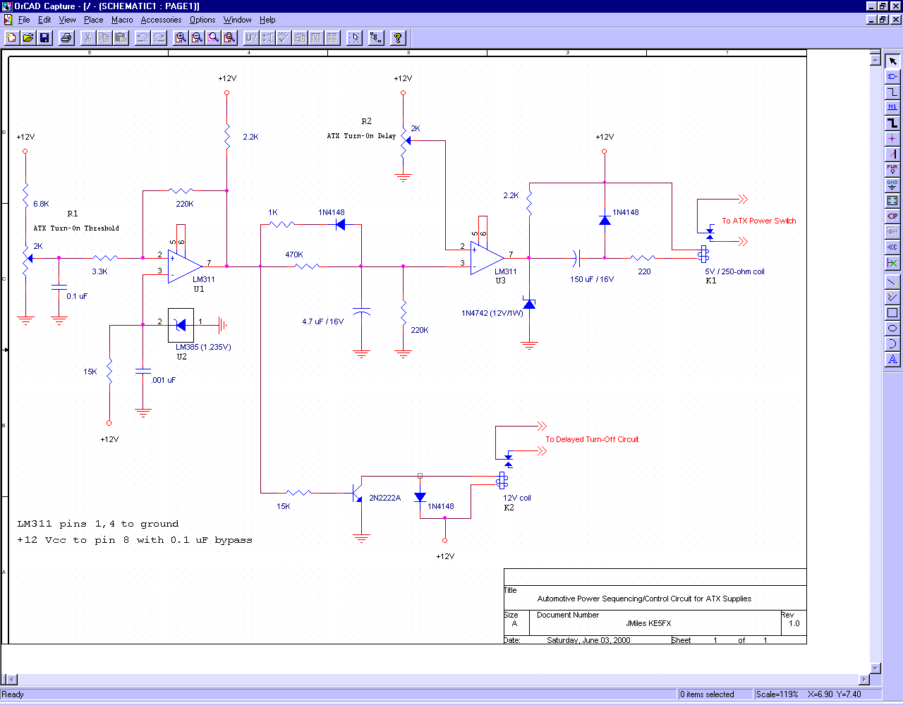
A standard 12-volt automotive electrical system can be viewed as a robust yet unreliable source of low-voltage DC current. Any mobile PC installation should encompass several features, as automotive systems must adhere to strict electrical standards. The starter motor...
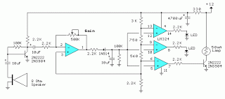
This decibel meter circuit responds to sound pressure levels ranging from approximately 60 to 70 dB (decibels). The sound is captured by an 8-ohm speaker and amplified using a transistor stage along with an LM324 operational amplifier section. A...
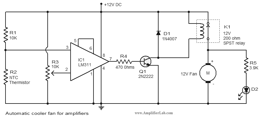
An automatic cooler fan for amplifiers is a circuit designed to conserve power in amplifier circuits. This circuit activates the fan. The automatic cooler fan circuit for amplifiers operates by utilizing temperature sensors to monitor the heat generated by the...
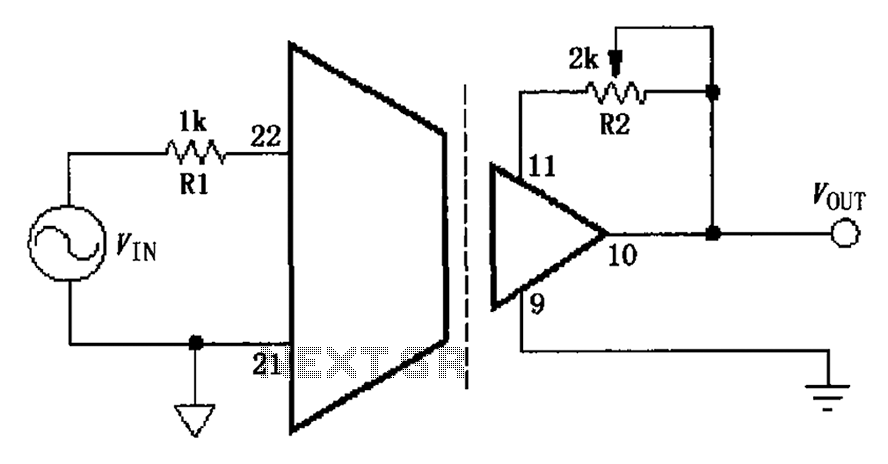
The gain adjustment circuit for the ISO103 is illustrated. The circuit features a gain trimming potentiometer, R2, which serves to enhance the gain accuracy and offset of the ISO103, thereby allowing for external adjustments. R2 provides a gain trim...
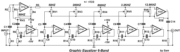
The EQ-2 is a 6-band graphic equalizer circuit. Each band is controlled by potentiometers RV1-6, which are designed as faders for improved visual indication of adjustments. However, standard potentiometers can also be used as replacements. At the center position...
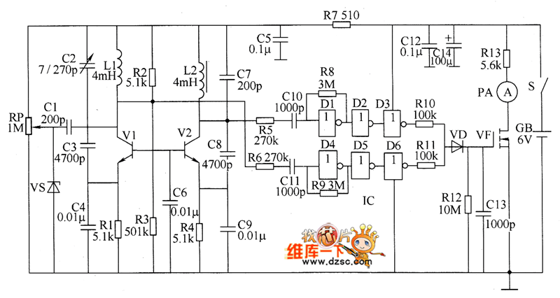
The metal detector circuit consists of several key components including the probe oscillator, reference oscillator, oscillation signal processor, mixing amplifier, and ammeter PA. The probe oscillator is made up of the oscillating tube VI, exploration coil L1, capacitors C1...