
12V power inverter using 555 timer circuit

This 12V power inverter circuit is designed to convert a low-voltage DC input into a higher-voltage AC output, making it suitable for powering standard household appliances from a car battery. The use of a 555 timer as an astable multivibrator is a notable feature of this circuit. This configuration allows for precise control over the frequency of the output waveform, which can be adjusted according to the needs of different devices.
The circuit begins with the 555 timer, which generates a square wave signal at a frequency determined by the values of the resistors and capacitors connected to it. This square wave signal is then used to drive the base of the transistors T1 and T2, which function as switches. When activated, these transistors allow current to flow through the primary winding of the output transformer, inducing a high-voltage AC signal in the secondary winding.
The output transformer plays a crucial role in stepping up the voltage from 12V to the desired 240V. The specifications of the transformer, including its turns ratio and core material, will significantly influence the efficiency and performance of the inverter. Additionally, the choice of driver transistors (T1 and T2) will determine the maximum load the inverter can handle, as their current and voltage ratings must be suitable for the intended application.
To ensure stable operation and prevent damage during load variations, it is advisable to include protective components, such as fuses or circuit breakers, in the design. Furthermore, incorporating filtering capacitors at the output can help smooth the waveform and reduce ripple, resulting in a cleaner AC signal.
Overall, this 12V power inverter circuit represents an effective solution for powering 240V devices from a 12V source, offering flexibility and adaptability for various applications.This 12V power inverter circuit can be used to power small power devices that need a 240 volts. This 12V power inverter circuit is very useful when you want to use a 240 volts consumer powered by a 12 volts car battery. In contrast to the usual feedback oscillator type of inverter, the oscillator of this inverter use a 555 timer connected as an
astable multivibrator that is separate from the output stage, which allows easy adjustment of the oscillator frequency to suit different applications. The output of the 555 timer drives the base of T1 and T2 transistors. The wattage of this 12 volts inverter circuit depend on the driver transistors and the output transformer used.
The output of this circuit will provide a 240v at 50Hz. 🔗 External reference
Related Circuits
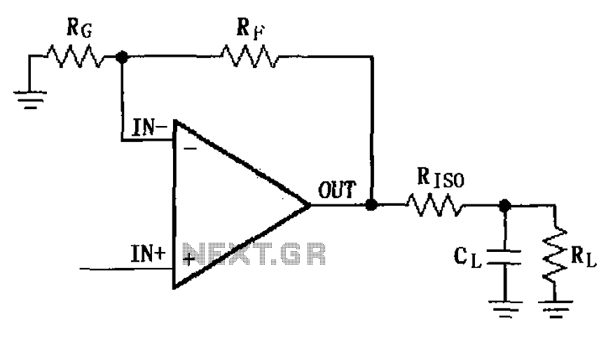
The MAX4223 to MAX4228 series incorporates a capacitive load drive circuit with an isolation resistor (RISO). The maximum allowable capacitive load for these devices is 25pF. However, exceeding this limit can lead to overshoot and ringing. The circuit design...
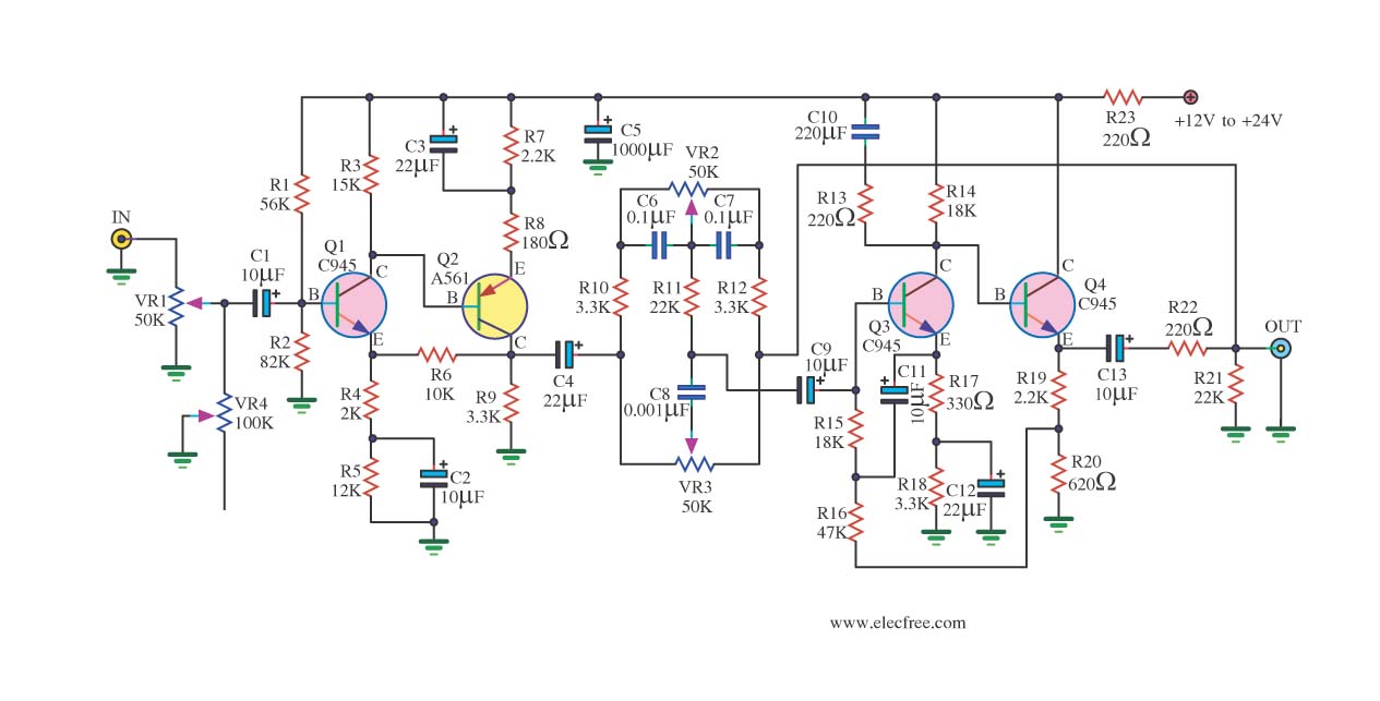
If you have old electronic equipment that has been around for many years, it is beneficial to build a good electronic project. Guidance is requested regarding a pre-tone control circuit for this purpose. A pre-tone control circuit is an essential...
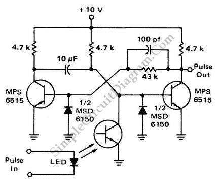
This is a flash-triggered (photo-driven) circuit that produces a pulse with a constant predetermined width. This circuit can be used to control any device. The flash-triggered circuit operates by utilizing a photodetector, which is typically a photodiode or phototransistor, to...
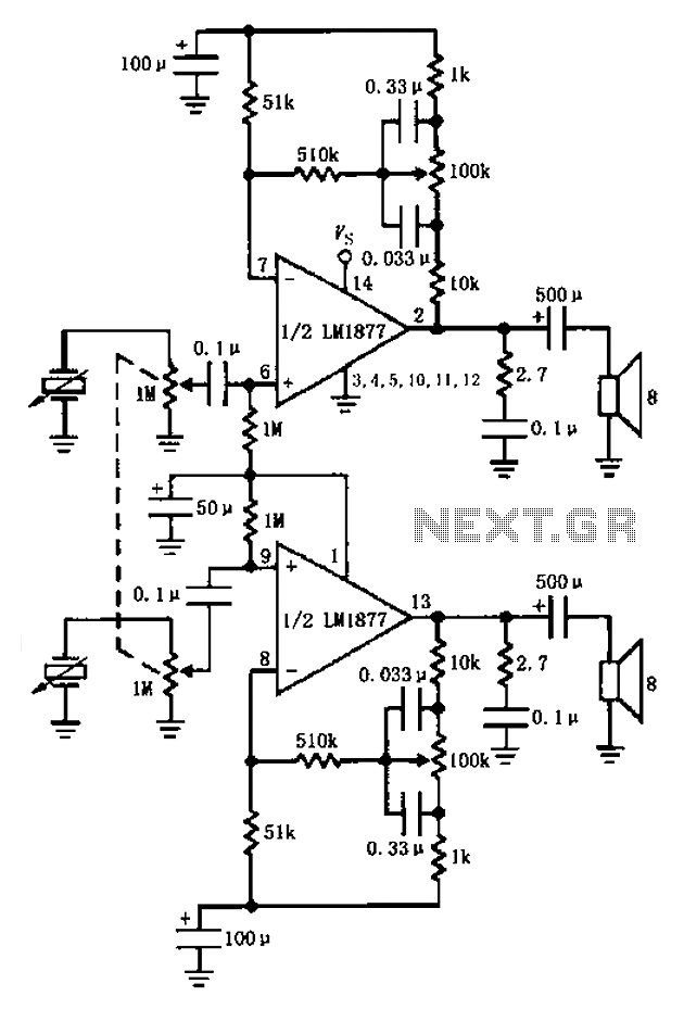
A bass player setup utilizing a stereo control is implemented through an LM1877 amplifier circuit. A cermet stereo microphone pickup is used to capture audio signals from a stereo turntable, with left and right channel outputs. The audio signals...
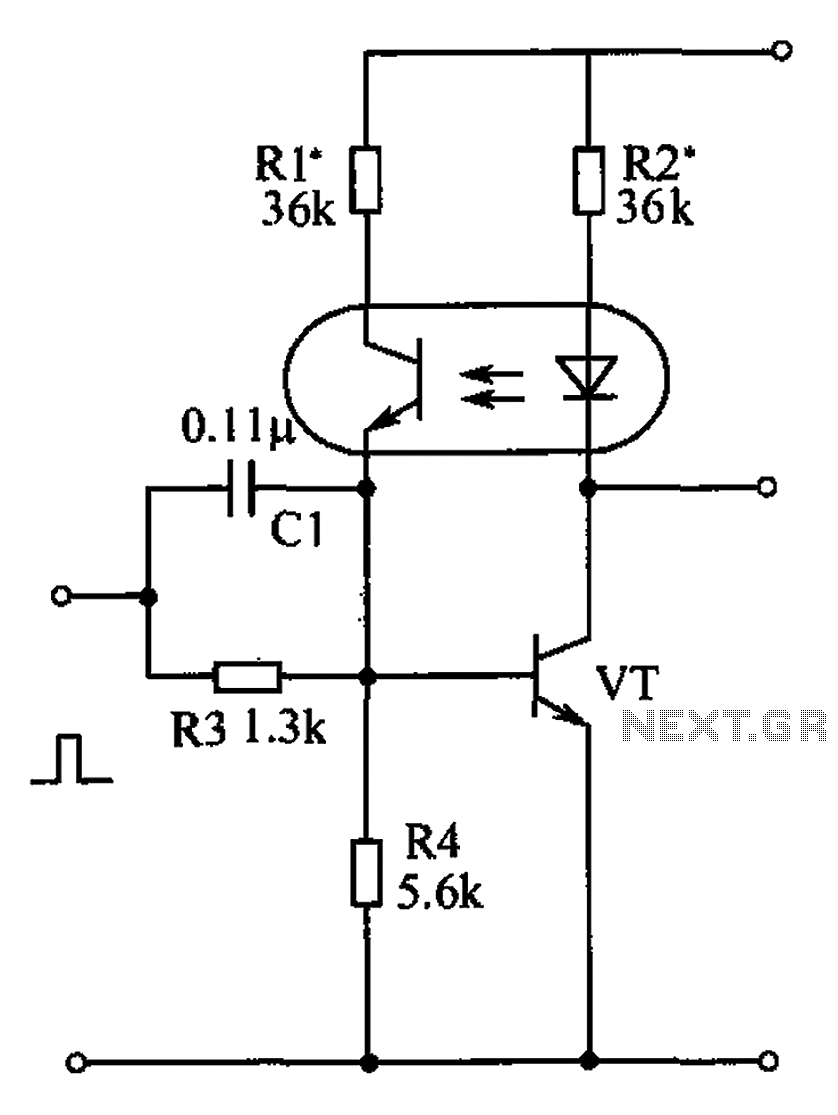
The bistable circuit and optocoupler transistor operate as illustrated in the accompanying figure. Initially, when the supply voltage is applied, the transistor VT is in the off state, resulting in a high output potential. Upon receiving a forward pulse...
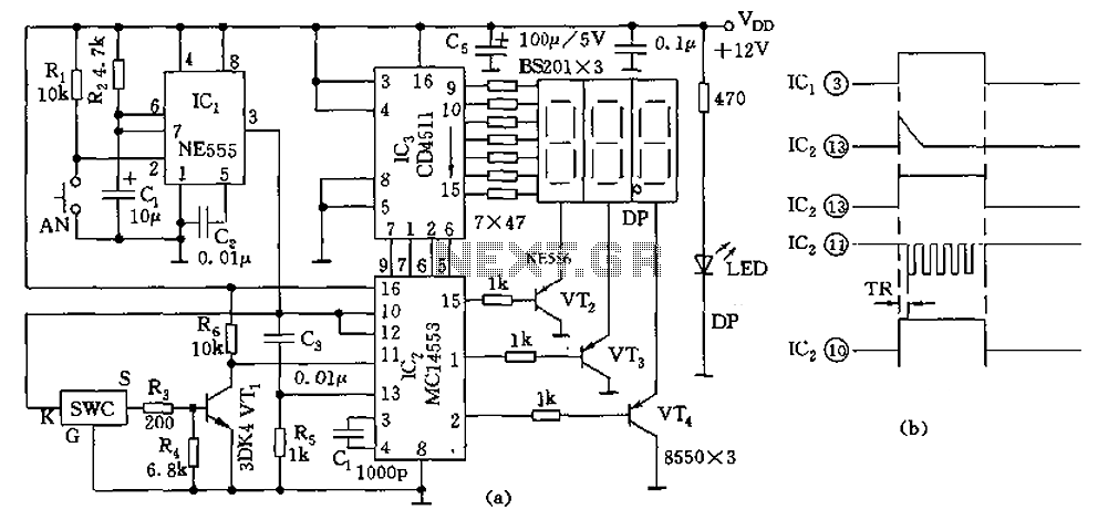
The digital thermometer consists of a temperature sensor, a single stabilizing circuit, a counter circuit, a decoding section, a driving circuit, and LED digital tubes among other components. It operates within a temperature range of 0 to 50 degrees...