
555 new digital thermometer circuit diagram

The digital thermometer circuit is designed with several key components that work in harmony to provide accurate temperature readings. The AD590 temperature sensor is integral to the system, providing a linear output proportional to the temperature. This sensor outputs a current that is converted to a voltage signal, which is then processed by the circuit.
The 555 timer (IC1) is configured in a monostable mode, generating a pulse width of approximately 50 ms that triggers the counting mechanism. The timing circuit is crucial as it establishes the frequency at which temperature readings are taken. The resistor R2 and capacitor C1 values determine this pulse width, and careful selection of these components is essential for the desired timing accuracy.
The BCD counter (IC2) counts the pulses generated by the 555 timer. The output of IC2 represents the digital value of the temperature, with each increment corresponding to a 0.1-degree Celsius change. The use of a BCD counter allows for straightforward interfacing with the seven-segment display, as it can directly drive the display through the CD4511 decoder/driver (IC3).
The CD4511 takes the BCD output from IC2 and converts it into signals that control the segments of the LED display, allowing the user to read the temperature in a clear and intuitive manner. The common cathode configuration of the display ensures that it operates efficiently with the output from the CD4511.
Overall, this digital thermometer circuit is a compact and efficient design that leverages widely available components to achieve high accuracy and reliability in temperature measurement, making it suitable for various applications in both industrial and consumer environments. As shown, the digital thermometer by the temperature sensor, single stabilizing circuit, counter circuit, decoding, driving and LED digital tube and other components. Temperatu re range of 0 to 50 degrees Celsius, 0.1 degrees Celsius accuracy, digital display. Line simple and intuitive. Temperature probe uses SWC digital integrated temperature sensor AD590 (or similar model). The device is a temperature-sensitive element and analog to digital converter (A/D) in one set, the amount of temperature is converted to digital, serial number of pulses indicates its temperature measured in degrees. Calibration Each pulse represents 0.1 degrees Celsius temperature increase, the response should be from 0 to 50 degrees Celsius from 0 to 500 output pulses.
Its conversion speed is less than 50ms, the positive and negative power supply voltage of 12V and 2V, the output pulse frequency 15kHz. According to measurement principle AD590 temperature sensor, it is easy to design a circuit diagram of a thermometer.
IC1 (555) and R2, C1 and other components single stabilization circuit generates timing width td 1.1R2C1, about 50ms shutter, added to the SWC and the K counter 10, 12 foot pole. IC2 with 3-digit BCD counter, the output of IC1 after C3, R5 differential, positive pulse as the pulse of IC2 count is cleared.
SWC add K-pole gate pulse 50ms after that start, serial pulse output, after amplification VT1, added 11 feet of IC2 counts. IC3 use BCD- seven latch/decoder/driver CD4511, the IC2 sent BCD code is decoded, and drive common cathode seven segment LED digital tube dynamic display.
Figure b is the main waveform diagram IC1, IC2s.
Related Circuits
This is a 100 Watt inverter circuit designed with a minimal number of components. The circuit utilizes the CD4047 integrated circuit from Texas Instruments to generate 100 Hz pulses, and it employs four 2N3055 transistors to drive the load....

The transistor characteristic curve tracer circuit depicted in Figure 555 illustrates the characteristics of a transistor. It utilizes two voltages: a step wave applied to the base (b) to generate different base currents (Ib), and a sawtooth waveform at...

The circuit for the RS232 serial interface exhibits mild complexity. The primary components of the circuit include the 18F4520 microcontroller, MAX233A level shifter, and a DB-9 connector. This circuit utilizes a basic +5V power regulator to supply the digital...

The first amplifier circuit is a bird phone. In this circuit, the electret microphone (MIC1) is mounted in the neck of a large plastic funnel. The amplifier, built around an MC34119, is then placed outside of the funnel with...

First Response Monitor, Input Selector, Game Circuit. This circuit is utilized for first response applications as it aids in monitoring various responses in games. The First Response Monitor circuit is designed to facilitate real-time monitoring and selection of input signals...
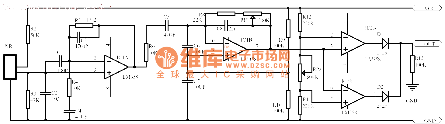
Passive human body infrared sensor circuits are generally similar in design, although some may have fewer stages. The circuit illustrated is sourced from the NICERA manufacturer and is considered a classic example. The front-end stage consists of a low-frequency...