
12v regulated inverter supply

To address the voltage fluctuations encountered when using lead-acid battery banks for 12V electronic devices, a voltage regulation circuit is essential. This circuit can be designed using a linear voltage regulator or a switching regulator, depending on the efficiency and heat dissipation requirements of the application.
A linear voltage regulator, such as the LM7812, can provide a stable output voltage of 12V. It operates by maintaining a constant output voltage despite variations in input voltage and load current. However, linear regulators are less efficient, particularly when there is a large difference between input and output voltage, as they dissipate the excess voltage as heat. Therefore, adequate heat sinking must be implemented to prevent thermal shutdown.
In contrast, a switching regulator, such as a buck converter, is more efficient for applications where the input voltage can be significantly higher than the desired output voltage. A buck converter steps down the voltage through a high-frequency switching process, allowing for greater efficiency and reduced heat generation. This is particularly advantageous when the battery voltage exceeds 14V during charging.
To implement such a circuit, the following components are typically included:
- A voltage regulator IC (either linear or switching type).
- Input and output capacitors to stabilize the voltage and filter noise.
- Inductors and diodes (for switching regulators) to manage energy transfer and rectify the output.
- Additional protection components such as fuses and surge protectors to safeguard against over-voltage and short-circuit conditions.
Incorporating a battery management system (BMS) can further enhance the reliability of the setup. The BMS monitors the state of charge, temperature, and health of the battery, ensuring that the batteries are not over-discharged or overcharged, which could lead to performance degradation or failure.
Overall, implementing a robust voltage regulation system will ensure that 12V electronic devices receive a stable and safe operating voltage, thereby enhancing performance and longevity.When running 12V electronic devices from lead-acid battery banks, the voltage to the appliance can vary from below 11V with discharged batteries, to well above 14V during charging. Many appliances will not tolerate such a wide fluctuation and may perform poorly or be damaged.. 🔗 External reference
Related Circuits
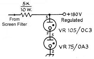
The power transformer features three secondary windings: 720V at 120mA center-tapped for the plate and screen supplies, 6.3V at 3.5A for the tube filament and bias power supply, and 5V at 3A (unused). Since the 5V secondary is not...
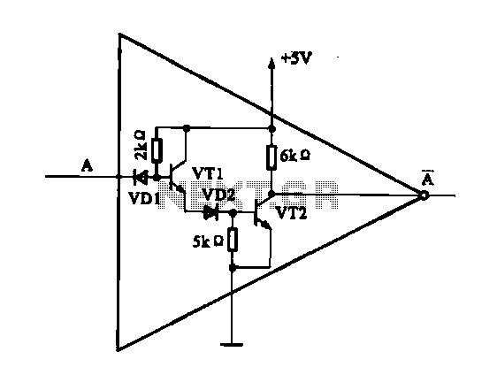
The internal structure of the DTL inverter circuit (M5936P) is composed of inputs with diodes and transistors for signal processing, powered by a +5V supply. When the input terminal A is at a high level (digital 1), diode VDI...
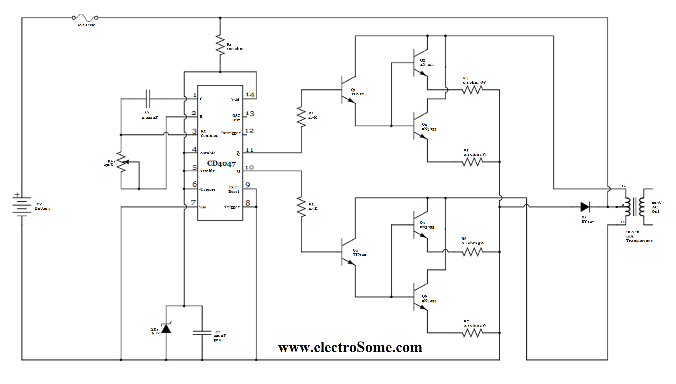
For basic requirements, square wave inverters can be utilized as they are simple, low-cost, and easy to construct. However, pure sine wave inverters are preferred for driving inductive loads. This document discusses a simple low-power square wave inverter using...
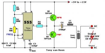
The 555 timer outputs a signal that is amplified by transistors Q1 and Q2 and fed into transformer T1, which is configured as a reverse-connected filament transformer with the appropriate step-up turns ratio. Capacitor C4 and inductor L1 serve...
A 6V to 12V DC converter circuit is designed to convert a lower voltage of approximately 6 volts to a higher voltage of 12 volts, albeit with a reduced current rating. This inverter circuit can deliver up to 800mA...
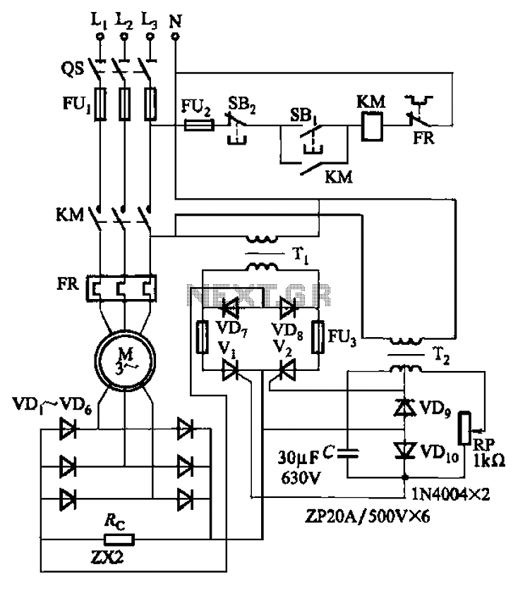
The circuit depicted in Figure 3-171 includes an auxiliary power supply that operates on single-phase AC power. It features a single-phase half-wave controlled bridge composed of diodes VD7, VD8, and thyristors V1, V2. The output current is managed by...