
Auxiliary power supply circuit using variable speed

The circuit operates using a single-phase AC power source, which is rectified by the half-wave controlled bridge. The controlled bridge consists of two diodes (VD7 and VD8) and two thyristors (V1 and V2). In this configuration, the diodes conduct during one half of the AC cycle, while the thyristors are triggered to conduct during the other half, allowing for control over the output voltage and current supplied to the load, which in this case is a motor.
The balancing resistor R is essential for ensuring that the output current is evenly distributed between the components of the bridge. This helps maintain stability in the circuit and prevents excessive current from flowing through any single component, thereby enhancing reliability and performance.
The thyristor trigger circuit is designed to provide precise control over the conduction angle of the thyristors. By utilizing a full-wave bridge configuration along with resistive and capacitive phase shifting, the trigger circuit can adjust the timing of the thyristor firing. The adjustment potentiometer RP allows the user to set the desired conduction angle, which directly influences the average output voltage and, consequently, the speed of the motor.
This circuit is particularly useful in applications requiring variable speed control, as it enables the motor to operate smoothly across a broad range of speeds from 300 RPM to 900 RPM. The ability to finely tune the speed through the adjustment of the conduction angle makes this circuit suitable for various industrial and automation applications where precise motor control is necessary. Circuit shown in Figure 3-171. The figure, the auxiliary power supply is single-phase AC power, the single-phase half-wave controlled bridge (diode VD7, VD8 and thyristor vl, V 2 composition) output current supply balancing resistor R. Thyristor trigger circuit is a full -wave bridge resistive and capacitive phase shift. Adjustment potentiometer RP, can change the trigger thyristor conduction angle, thereby enabling the motor can be 300 ~ 900r/min continuously adjustable within range.
Related Circuits
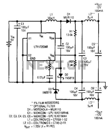
An LT1172 generates positive and negative voltages from a 5-V input. The LT1172 is configured as a step-up converter. To generate the negative output, a charge pump is used. C2 is charged by the inductor when D2 is forward-biased...
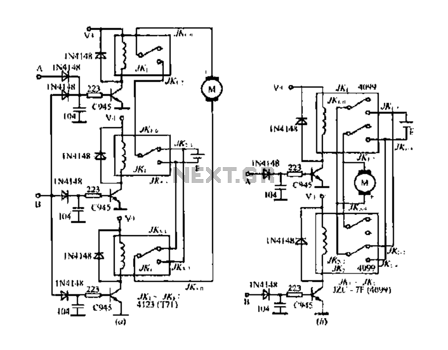
The DC motor E inversion control circuit utilizes a loop configuration with various relay contacts. It employs a single set of normally open/normally closed relay contacts. When both inputs A and B are low, relay KI is activated. In...
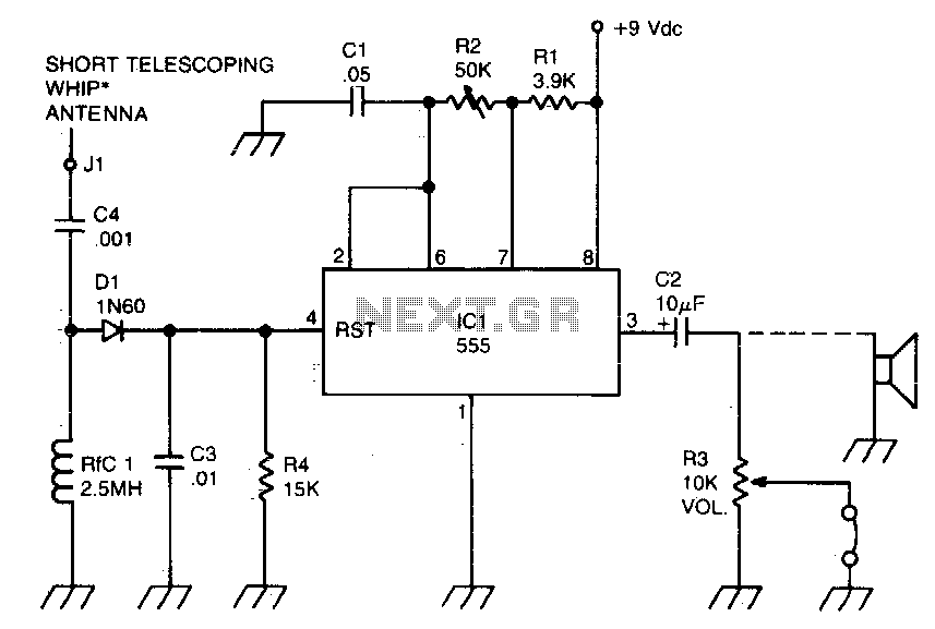
A sidetone oscillator is a specific type of audio astable multivibrator. Keying is achieved by turning the oscillator on and off through the application of a positive DC potential, which is generated from the RF signal to the reset...
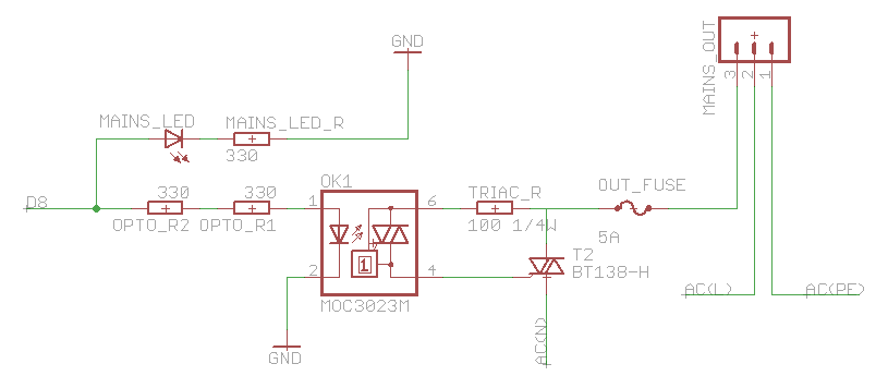
The heatsink on the triac is somewhat unclear. A maximum value of 10°C/W has been calculated, which raises concerns. The calculation is as follows: (maximum temperature - room temperature) / (maximum on-stage voltage * (milliamps / voltage) - junction-to-base...
AN79 Linear Technology AN79 modifies methods presented in AN74, allowing for the verification of 30 nanosecond amplifier settling times with 0.1% resolution. The sampling-based technique used is detailed, and results are presented. Appendices cover oscilloscope overdrive issues, the construction...
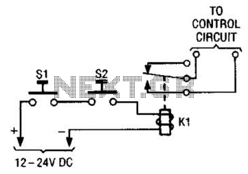
The simple two-hand safety control switch consists of two pushbutton switches connected in series; both must be depressed to energize the relay. The two-hand safety control switch is designed to enhance safety in applications where the operation of machinery or...