
Relay control auto-transformer AC power supply circuit

The circuit employs the LM358, a dual operational amplifier, to compare two voltage levels. The first op-amp (A2) is configured to monitor the upper limit voltage, while the second op-amp (Ar) monitors the lower limit voltage. The output of these op-amps will indicate whether the measured voltage exceeds the upper limit or falls below the lower limit.
The potentiometer labeled RPi is connected to the non-inverting input of A2, allowing users to adjust the reference voltage to set the desired upper limit. Similarly, the potentiometer RP2 is connected to the non-inverting input of Ar for adjusting the lower limit voltage. The inverting inputs of both op-amps are connected to the voltage being measured, which is compared against the set reference voltages.
When the measured voltage exceeds the upper limit, the output of A2 will switch to a high state, indicating an over-voltage condition. Conversely, if the measured voltage drops below the lower limit, the output of Ar will switch to a high state, signaling an under-voltage condition. This dual comparison setup enables effective monitoring of voltage levels and can be used in various applications, including power supply regulation, battery management systems, and safety alarms.
The circuit can be further enhanced by integrating additional components such as LEDs or relays that can be activated based on the op-amp outputs, providing visual or physical indications of voltage status. This design ensures that the system can react promptly to voltage deviations, maintaining operational safety and reliability.It uses two LM358 op amp A2 and Ar as an upper limit and a lower limit voltage electrical voltage measurement comparison control circuit. RPi adjustment potentiometer and RP2, can change the upper limit voltage and lower voltage setting.
Related Circuits
The receiver is based on a basic SA612 circuit. The local oscillator (LO) for the 20-meter band operates at approximately 9 MHz, with an intermediate frequency (IF) of 5.068 MHz. The IF filter employs two crystals and has a...
The code implementation discussed in the previous post has been initiated. To improve organization, the code has been modularized into functions, simplifying the overall structure. It is available along with the other code. Challenges were encountered in calculating averages...
To order boards, click to access the ESP Purchase form. Verify the price and postage, then open the order form, fill it in, and print it from your browser. Boards are sold only as a stereo pair and are...
This is a simple NiCd battery charger powered by solar cells. A solar cell panel or an array of solar cells can charge a battery at more than 80% efficiency. The described circuit functions as a basic NiCd battery charger...
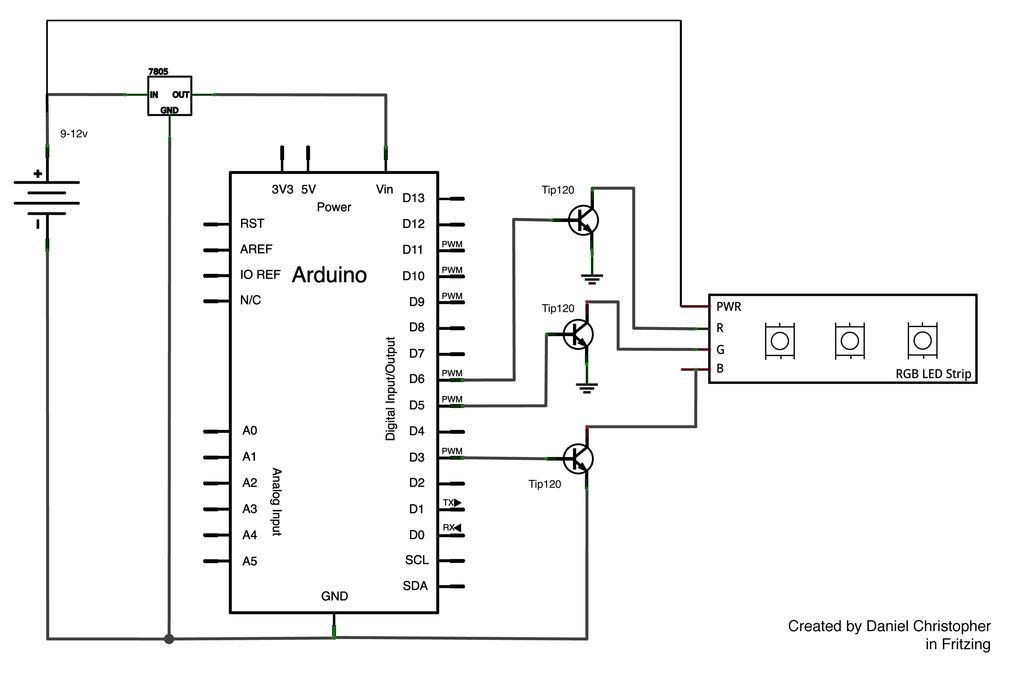
This document outlines the assembly of a circuit designed to pulse width modulate (PWM) a high-power RGB LED strip and program an Arduino to cycle through various colors. The high-power range is specified as 9-12 volts. The procedure includes...
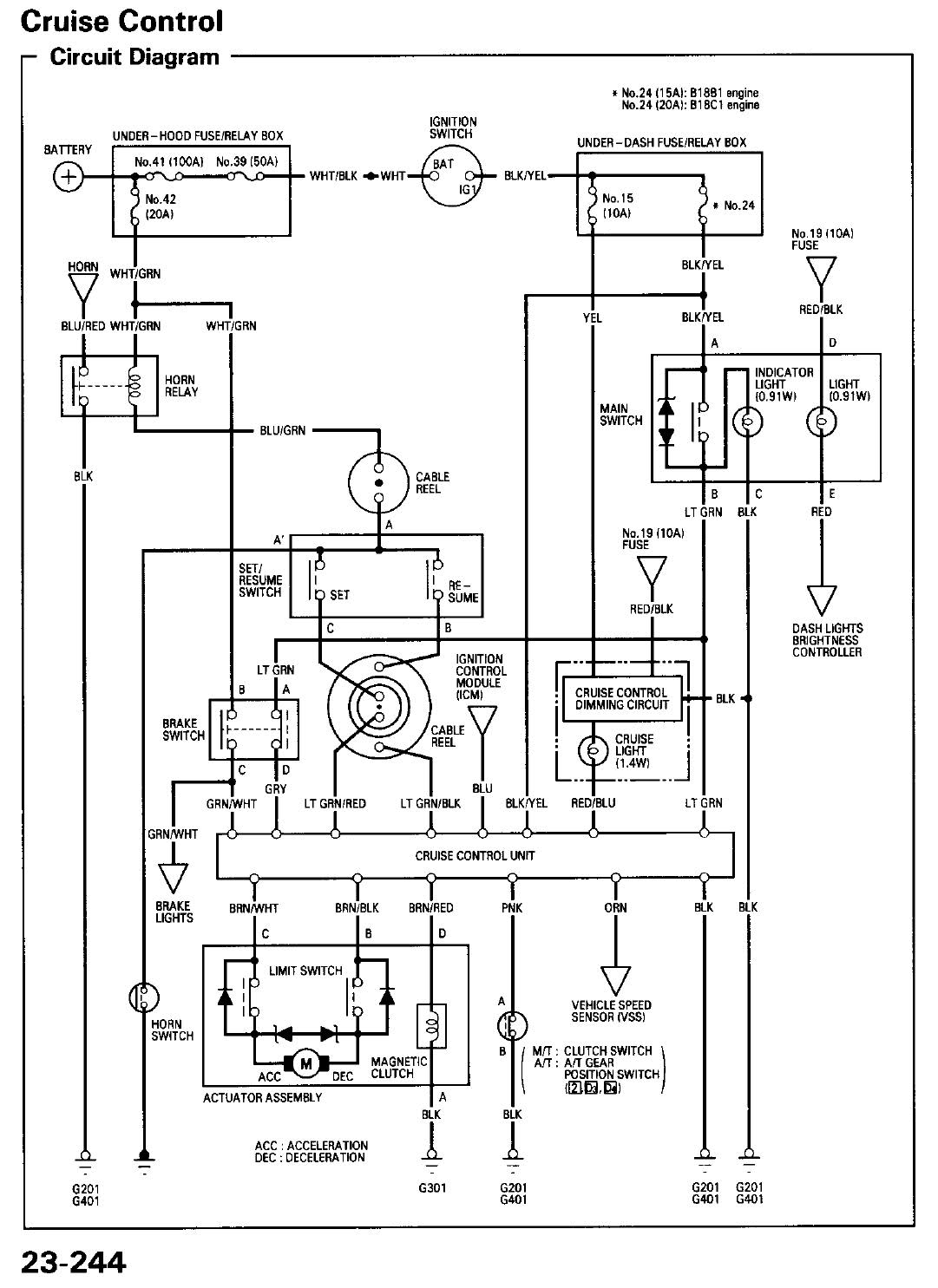
A quick search did not yield much information regarding the wiring diagram for cruise control systems in vehicles, specifically for models from 1994 and onward. The cruise control system in vehicles typically consists of several key components, including the...