
12v to 3v converter

The 12V to 3V converter circuit is typically designed using a linear voltage regulator or a buck converter topology. The choice between these methods depends on the application requirements, such as efficiency, heat dissipation, and load characteristics.
For a linear voltage regulator approach, a common component used is the LM317 adjustable voltage regulator. This regulator can output a stable 3V with the appropriate resistor values configured at its adjustment pin. The circuit requires input capacitors to filter the 12V supply and output capacitors to stabilize the voltage. The thermal performance must also be considered, as the difference between input and output voltage (9V in this case) will dissipate power as heat, which may require a heat sink.
Alternatively, a buck converter can be employed for higher efficiency. This switch-mode power supply (SMPS) utilizes an inductor, a diode, and a switch (typically a MOSFET) to convert the higher input voltage to a lower output voltage with minimal power loss. The circuit design will include feedback control to maintain the desired output voltage despite variations in load current. Inductor selection, switching frequency, and output capacitor sizing are critical parameters that influence the performance and efficiency of the converter.
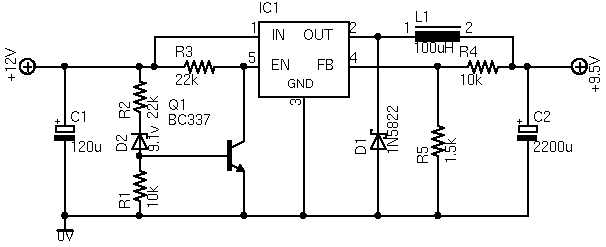
In both configurations, it is essential to ensure that the components are rated for the expected load current of 1A. Proper PCB layout techniques should be applied to minimize noise and ensure stable operation. Additionally, input and output filtering capacitors may be included to further improve transient response and reduce ripple voltage at the output.Here is a very simple and useful project / schematic of a 12V to 3V converter circuit. The output current of the circuit is around 1A.. 🔗 External reference
Related Circuits
This converter is useful when only the serial port on a personal computer is available, while the printer requires a parallel (Centronics) port. It converts a serial signal at 2400 baud into a parallel signal. The TxD line (pin...
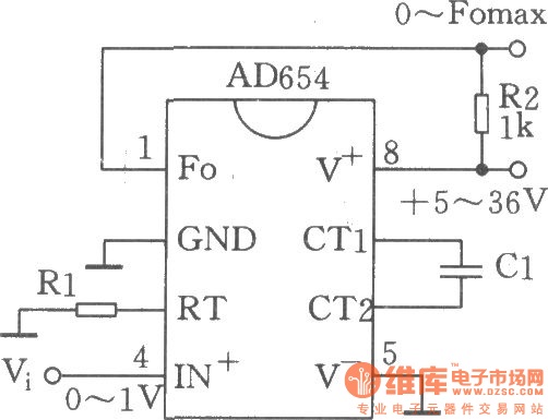
The circuit depicted is a low-cost voltage frequency converter (VFC) utilizing the AD654 component. By connecting the required components, Rl and Cl, as shown in the figure, a functional VFC application circuit can be established. The supply voltage can...

This design circuit is a tachometer circuit based on the LM2907 integrated circuit, which can provide zero-crossing data to a digital system. At each zero crossing of the input signal, the charge pump alters the state of capacitor C1...
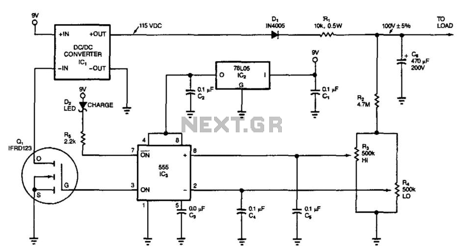
This circuit switches its DC/DC converter, IC1, off whenever the large filter capacitor, C6, has sufficient charge to power the load. This particular circuit uses a DC/DC converter that produces 115 Vdc from a 9 Vdc input; it can...
The listed currents represent maximum values, and the actual current consumption will vary based on the circuit's operation. This precludes the simple use of a resistor in series to reduce voltage from 12 volts to 9 volts for powering...
The ASUS Eee is an ultra-portable notebook designed for tech enthusiasts, offering essential features without unnecessary extras. It boasts excellent build quality and is competitively priced. In New Zealand, it can be purchased exclusively from DSE, making it cost-effective...