
mk120 light barrier 12v dc power supply

The circuit design involves managing multiple voltage levels to accommodate different components effectively. The use of the LM7809 voltage regulator is advantageous for stepping down the voltage from 12 volts to a stable 9 volts, which is essential for circuits sensitive to voltage variations. The LM7809 is a linear voltage regulator that can provide a maximum output current of 1.5 A and has built-in thermal overload protection, which is critical given the heat generation concerns noted with the LM338 regulator.
The presence of the 1N4007 diode in the circuit introduces an additional voltage drop, which must be accounted for in the design. The forward voltage drop of approximately 0.6 volts means that the effective voltage supplied to the circuit is around 8.4 volts when powered from a 12-volt source. This aspect is crucial to ensure that all components receive adequate voltage for optimal performance.
In terms of layout, a dual power supply design is beneficial for isolating the LED circuit from the motor circuit. Motors, especially when controlled by PWM drivers, can introduce electrical noise that may affect sensitive components like LEDs. By employing a separate LM338T constant current circuit for the LEDs, the design mitigates the risk of noise interference, thus enhancing the reliability and performance of both circuits.
When considering the possibility of sharing a single power supply, it is essential to implement adequate decoupling capacitors and possibly ferrite beads to filter out noise and transients that may arise from the motor circuit. Proper grounding techniques and layout considerations will further ensure that the two circuits can coexist without adverse effects on performance.
In conclusion, this design emphasizes the need for careful voltage management, thermal considerations, and noise reduction strategies to create a reliable and efficient circuit that meets the operational requirements of the various components involved.The currents listed are maximum values, the actual current used will vary on what the circuits are doing. That precludes just placing a resistor in series to drop 12 to 9 volts and run the units. Note that on each circuit there is a 1N4007 diode in series with the power. That diode will drop about. 6 volt leading me to believe the actual circuits run on less athn 9 volts and more like 8. 4 volts approximately. My choice would be to use a few LM7809 regulators to give you 9 volts from a 12 volt source. The data sheet can be found here. That is how I would likely go about it. Thanks for you suggestion, I use LM338 as voltage regulator (see picture) now and since it gets very hot I was thinking to use 12V somehow. My main voltage used by this project is 12V for motor, LED etc. Only this circuit needs 9V. I have made dual PSU to reduce noise from motor circuit (with PWM driver) to the LED circuit (another LM338T constant curren circuit).
Or perhaps they can share same PSU without any issues 🔗 External reference
Related Circuits
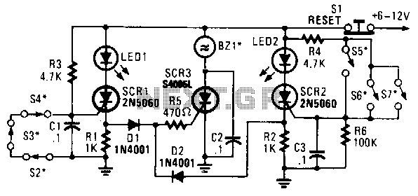
In this circuit, a low-powered silicon-controlled rectifier (SCR) is utilized to trigger a higher-powered SCR. When a switch is opened (S2, S3, S4) or closed (S5, S6, S7), either SCR1 or SCR2 is activated. This action subsequently triggers SCR3...
A complementary transistor pair (Q2 and Q3) is configured as a high-efficiency oscillator that directly drives the loudspeaker. Q1 is responsible for fully charging capacitor C2 when power is applied to the circuit. When switch P1 is pressed, C2...
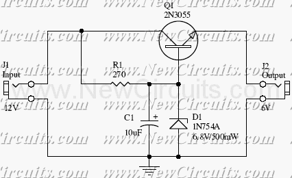
This small but useful circuit is a DC voltage converter for using 6V devices with car battery voltage. The maximum output current is dependent if the T1 is covered with a proper heat sink or not. You can use...
This circuit utilizes the TA7222AP to amplify audio signals. The cost is only $0.99, and it can provide 5.8 watts with muting control. The power supply can be in the range of 8-12 VDC, making it suitable for applications...
The circuit utilizes relay control. The voice switch operates as follows: upon the first clap, the load (lights) is activated; upon the second clap, the load (lights) is deactivated. This system can be employed to control lighting in residential...
The following circuit illustrates the connection of the Devantech SRF04 Ultrasonic Sensor to the SV203 powered PPRK Circuit Diagram. This circuit is based on the Devantech SRF04 sensor and features a minimum initiation time of 10 milliseconds for the...