
A 12V Car Charger For ASUS Eee Notebook

The circuit design for the DIY car charger for the ASUS Eee notebook focuses on converting a car's 12V supply to the required 9.5V output. The heart of the circuit is the LM2576, a step-down (buck) regulator, which is suitable for high current applications. The LM2576 operates with a switching frequency that necessitates the use of a larger inductor, which is critical for energy storage and regulation. The selected inductor, PE92108KNL, must handle the load current efficiently while ensuring minimal energy loss.
The circuit layout should include input and output capacitors to stabilize the voltage levels and reduce ripple. Input capacitors should be rated for high temperatures and low Equivalent Series Resistance (ESR) to enhance performance. The low voltage cut-out circuit prevents the charger from operating under insufficient voltage conditions, which could lead to erratic behavior or potential damage to the notebook. The use of a Zener diode for voltage reference and a transistor for switching provides a reliable method for monitoring input voltage levels.
Thermal management is crucial due to the high current flow through the LM2576. Heat sinks may be necessary to dissipate heat generated during operation, ensuring the longevity and reliability of the charger. The overall design should consider the physical layout to minimize the size while accommodating the larger components required for the high current output.
In summary, the DIY car charger project serves as a practical application of power electronics principles, utilizing a buck converter design to meet the specific needs of the ASUS Eee notebook while providing insights into component selection, thermal management, and circuit stability.The ASUS Eee is a fantastic ultra-portable notebook with almost everything required for geeks (and nothing that isn`t). Plus it features fantastic build quality and is very well priced. If you live in New Zealand you can get them from DSE ; at the time of writing they are the exclusive supplier.
I worked out it`s the same cost as importing one onc e you include all the duties and tax, plus you get the advantage of a proper NZ-style mains charger. Anyway, being so small I thought it would be nice to be able to carry this around in the car. Unfortunately I couldn`t find a car charger available anywhere at the time so I decided to tackle the problem myself. As a bonus this provides an opportunity for an external high-capacity battery. I thought at this stage it would be worth noting that a commercial car charger is now available for less than it cost me to build this from Expansys and is available in most countries (select your location on their site).
It outputs 9. 5v from 10-18v in at up to 2. 5A. I`d actually recommend it over the design here is it seems to perform better at lower voltages (that one works down to 10V). However I have kept this page up as a reference for those who enjoy tinkering. The charger included with the Eee is rated at 9. 5v, 2. 315A. There isn`t a fixed voltage regulator available for this exact voltage, so the circuit needed to be designed around an adjustable regulator.
I decided to design the charger around the LM2576 Simple Switcher IC from National Semiconductor. There are tons of ICs like this available, many of which are a bit more efficient, however I selected this one because it is readily available and relatively cheap. It also has a lower drop-out voltage (~2V) than many other chips I looked at which is important when powering the device from a car or 12v SLA battery.
This circuit could have used a standard three pin regulator IC such as the LM317, however most types require an external transistor when handling so much current and not to mention the fact that they are very inefficient; they draw the same amount of current from the input as the load and the difference in power is dissipated as heat. The main problem with using the LM2576 is the fact it needs quite a large inductor due to its somewhat low switching frequency.
The inductor I used is made by Pulse Engineering, part number PE92108KNL. I`d prefer a smaller one, however I couldn`t find one capable of supplying the required current that I could purchase in single units. Besides the PE92108KNL is apparently designed specifically to work with the LM257x series. The circuit also includes a low voltage cut-out based on a 9. 1v Zener diode and BC337 transistor that will shut down the regulator if the input voltage is below 11.
5V. This prevents unstable operation of the regulator at lower input voltages, and also helps prevent accidental flattening of the supply battery. Substituting this transistor for similar type may affect the cut-out voltage; the Vbe of the transistor should be 1.
2v. All of the components used should be pretty readily available in most areas. I got everything from Farnell. Jaycar also sells everything except the inductor. Make sure you specify high temperature, low ESR capacitors as these help result in more stable operation and better efficiency of the charger. Unfortunately the end result is a charger that is slightly bulkier than I would really like. I attempted to fit this inside an old mobile phone charger case so the whole thing could hang out of the cigarette lighter, however I ran into trouble making the circuit stable enough and dissipating all the heat.
Due to the high current involved compared to a mobile phone charger the components are much bulkier so it`s pretty tricky to get all to fit! If I do get it finished I`ll add an update. 🔗 External reference
Related Circuits
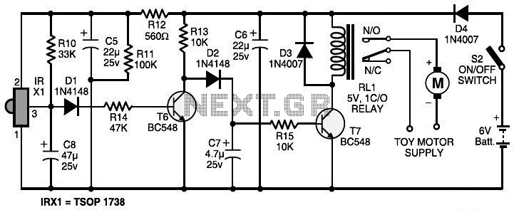
The circuit features an infrared transmitter-receiver pair that uses infrared beam transmission to turn the toy car on or off. It is designed for simple operation, with potential modifications to enable the toy car to turn left or right....
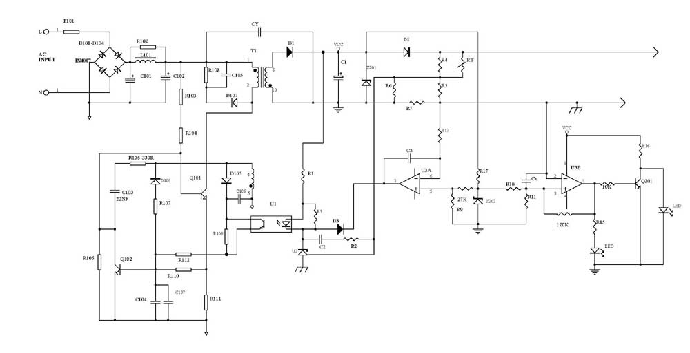
Several schematic drawings of battery charger circuits are provided. These circuits cover 5W to 200W for NiCd, NiMH, Lead-Acid, Li-Ion/Polymer, and LiFePO4 battery packs. The charger circuit files aim to assist users in selecting the appropriate chargers and to...
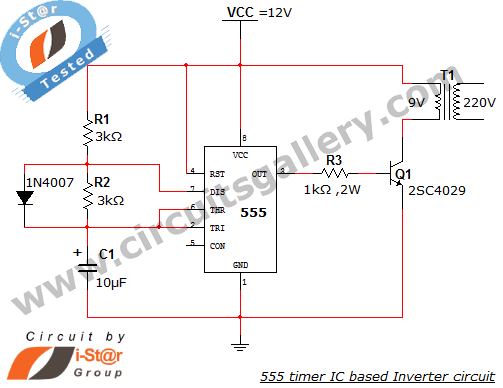
This article explains what an inverter is and how to construct a simple, low-cost 12V to 220V inverter circuit. An inverter functions as a DC to AC converter and is a valuable electronic product for compensating for emergency power...
The circuit utilizes a thermistor and three sections of a LM3900 quad operational amplifier (op amp) integrated circuit. When the temperature decreases to 36°F, an LED indicator flashes approximately once per second. As the temperature continues to drop to...
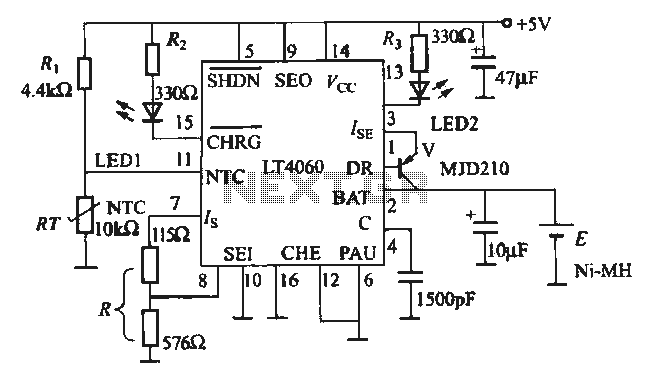
The charging circuit is designed for rechargeable batteries, particularly for situations where high charging currents can lead to increased temperatures. The LTC4060 includes an external thermistor that detects the charging temperature to prevent overheating. This device operates as a...
A circuit breaker is an electronic device that functions to protect an electrical circuit from hazards or damage caused by overloads or short circuits. A circuit breaker operates by automatically interrupting the flow of electricity when it detects an...