
12V to 6V Converter

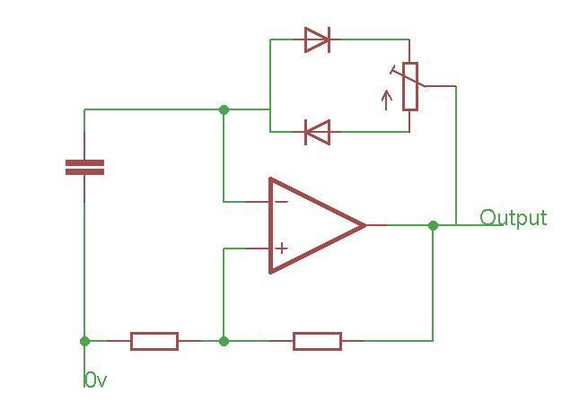
The circuit described functions as a DC voltage converter, specifically designed to step down the higher voltage of a car battery (typically around 12V to 14.4V) to a stable 6V output suitable for powering devices that operate at this lower voltage. The core component of the circuit is a voltage regulator, often represented as T1 in the description.
To ensure optimal performance, it is critical to manage the thermal characteristics of the regulator. When T1 is equipped with an appropriate heat sink, it can handle a significantly higher output current of up to 5A. Without a heat sink, the maximum output current is limited to 0.5A due to thermal constraints, which could lead to overheating and potential damage to the regulator.
The circuit typically includes input and output capacitors to filter out voltage spikes and maintain stability. The input capacitor smooths the incoming voltage from the car battery, while the output capacitor ensures a steady voltage supply to the load. Additional components such as diodes may be included to prevent reverse polarity and protect the circuit from potential damage.
This voltage converter circuit can be utilized in various applications where 6V devices need to be powered from a car battery, such as powering LED lights, small motors, or other electronic devices designed for 6V operation. Proper design considerations, including the selection of T1 and the sizing of the heat sink, are essential to ensure reliable operation and longevity of the circuit.This small but useful circuit is a DC voltage convertor for using 6V devices with car battery voltage. The maximum output current is dependent if the T1 is covered with a proper heat sink or not. You can use the circuit to drive devices that they sink maximum 0.5A current without any heat-sink and 5A with a large heat-sink.
🔗 External reference
Related Circuits
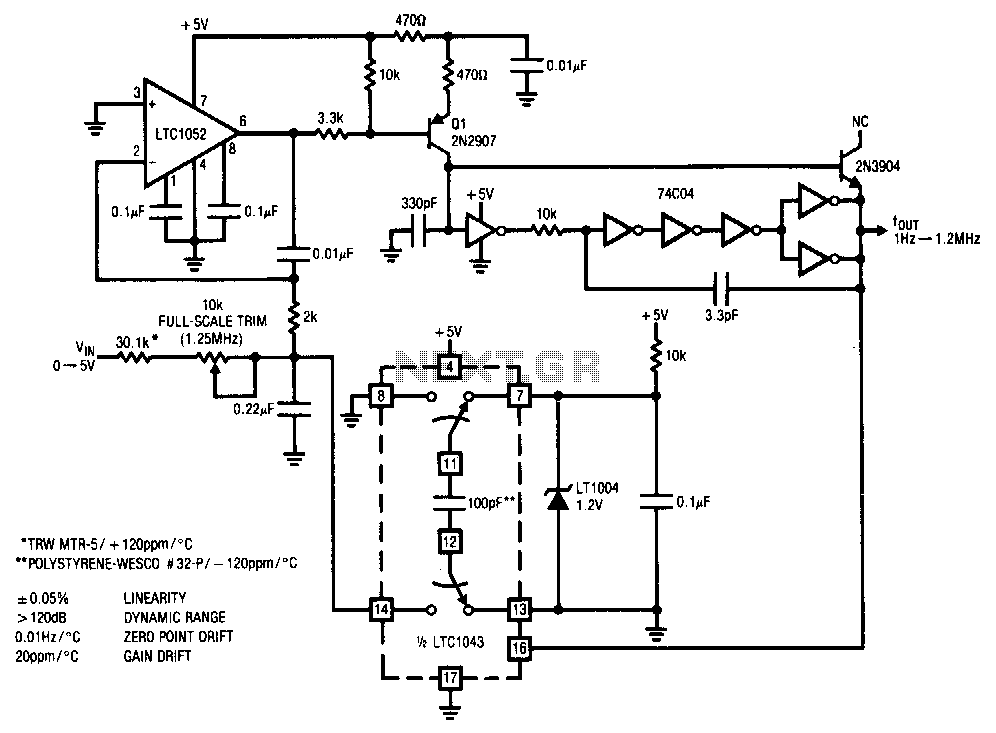
This stabilized voltage-to-frequency converter operates within a range of 1 Hz to 1.25 MHz, featuring a linearity of 0.05% and a typical temperature coefficient of 20 ppm/°C. The circuit is powered by a single 5-V supply. It employs a...
The LT3465/LT3465A are step-up DC/DC converters designed to drive up to six LEDs in series from a Li-Ion cell. Series connection of the LEDs provides identical LED currents and eliminates the need for ballast resistors. These devices integrate the...
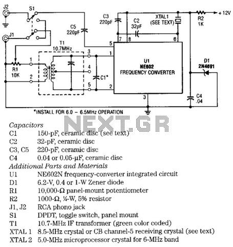
The NE602 chip, U1, contains oscillator and mixer stages. The mixer combines the oscillator signal with the input RF signal to produce signals whose frequencies are the sum and difference of the input frequencies. For example, an 8.5-MHz oscillator...
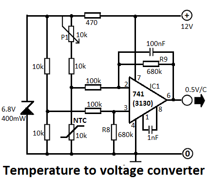
This simple temperature-to-voltage converter circuit allows for precise measurement of room temperature using an NTC resistor or thermistor. The temperature-to-voltage converter circuit typically employs a negative temperature coefficient (NTC) thermistor, which exhibits a decrease in resistance as temperature increases. This...
A portable 50W light operates using a 12V 7Ah battery. There are instances when the light output is excessively bright, prompting an inquiry into the necessary components to reduce the brightness. To address the issue of excessive brightness in a...
Before World War II the FM radio band was just below 50 Mc. Read all about it. If you have such a radio, you might want to build this converter. It will let your old set receive the modern...