
12V light dimmer

To address the issue of excessive brightness in a portable 50W light powered by a 12V 7Ah battery, several circuit components can be utilized for dimming or brightness control. A common approach is to implement a pulse-width modulation (PWM) dimmer circuit. This circuit allows for adjustable brightness by varying the duty cycle of the power supplied to the light.
Key components for a PWM dimmer circuit include:
1. **Microcontroller or PWM Controller**: A microcontroller (such as an Arduino) or a dedicated PWM controller IC can be used to generate the PWM signal. The frequency of the PWM signal should be high enough (typically above 1 kHz) to ensure smooth dimming without flickering.
2. **MOSFET or Transistor**: A MOSFET (Metal-Oxide-Semiconductor Field-Effect Transistor) or a suitable power transistor can be used as a switch to control the current flowing to the light. The chosen MOSFET should be capable of handling the current load of the 50W light at 12V, which is approximately 4.17A.
3. **Resistors**: Resistors may be required for current limiting and to set the PWM frequency if using a microcontroller. Additionally, a pull-down resistor can ensure the MOSFET turns off completely when the PWM signal is low.
4. **Capacitor**: A capacitor may be included in the circuit to smooth out the PWM signal, reducing potential flickering and providing a more stable output.
5. **Potentiometer**: For manual brightness adjustment, a potentiometer can be integrated into the circuit, allowing the user to adjust the duty cycle of the PWM signal. This adjustment will directly affect the brightness of the light.
6. **Heat Sink**: If the MOSFET or transistor dissipates significant heat during operation, a heat sink should be added to prevent overheating and ensure reliable operation.
By integrating these components into a PWM dimming circuit, the brightness of the 50W light can be effectively controlled, providing flexibility for various lighting situations while maintaining efficient power usage from the 12V 7Ah battery.I have a portable 50W light that is run off a 12V 7Ah battery. In some cases the light is too bright so i was wondering what parts i would need to mak.. 🔗 External reference
Related Circuits
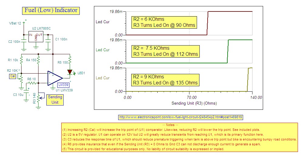
Research indicates that the sender will register a resistance of 100 ohms when the fuel tank is empty, making a trigger reading of 80 ohms optimal. The fuel gauge sender is a critical component in monitoring the fuel level within...
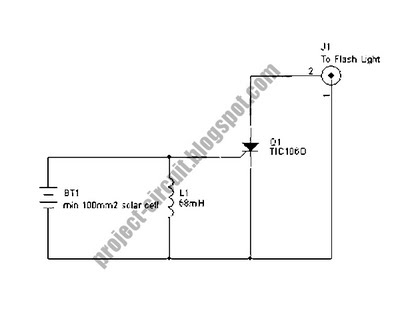
The following circuit illustrates a Slave Flash Light Control Circuit Diagram. Features include a 68 mH inductor, which provides an automatic trigger for the secondary flash light. The Slave Flash Light Control Circuit is designed to enhance the functionality of...
This simple dimmer consists of only two components and can be easily integrated into a mains switch. It is essential to first switch off the associated branch circuit in the fuse box, as mains voltage poses a danger. The...
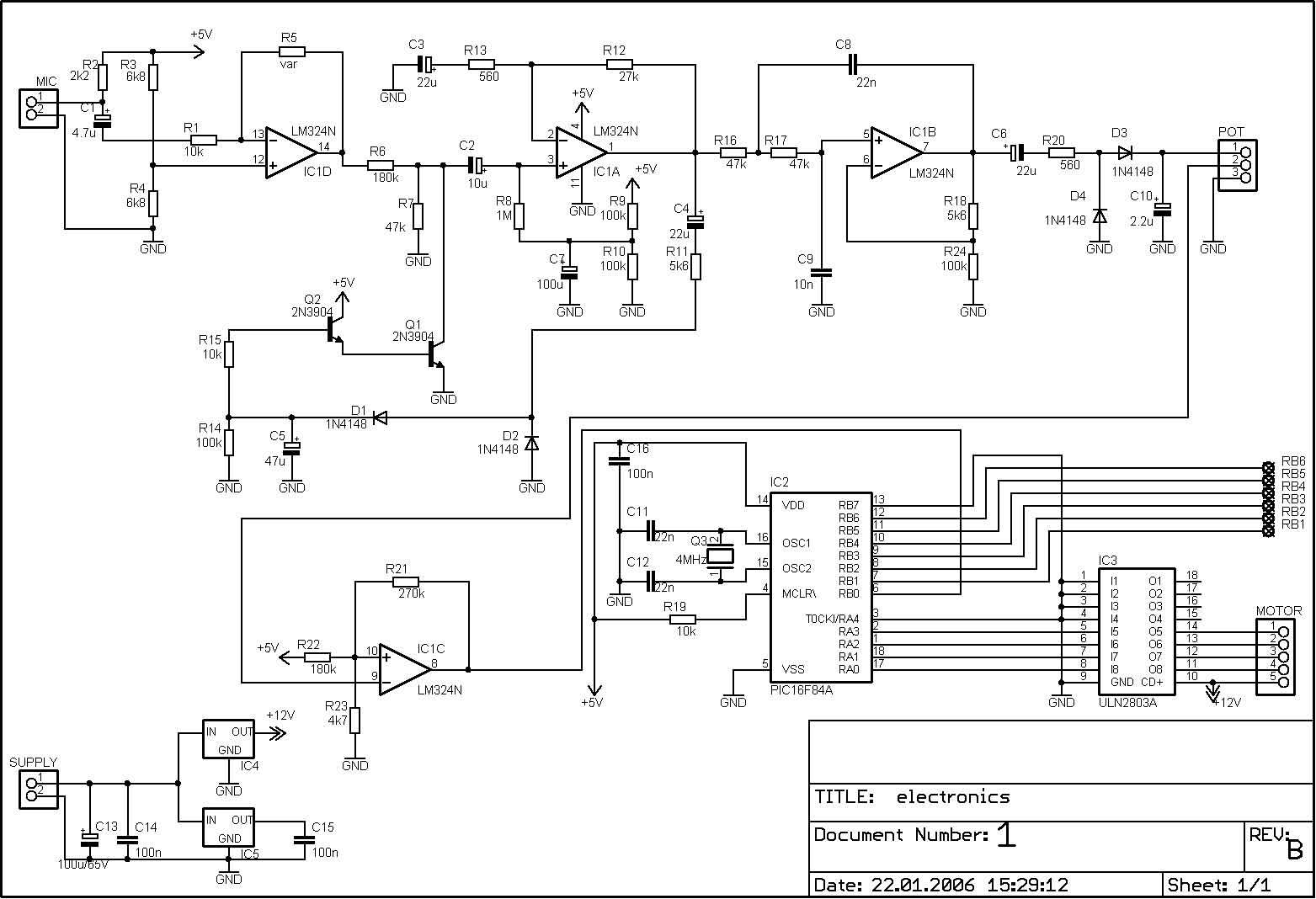
The PIC microcontroller is capable of controlling a motor after each beat, with the option to bypass certain beats using pushbuttons. The rotation speed and duration can also be adjusted within specified limits to prevent register overflow or underflow....
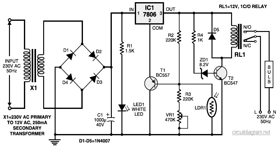
During nighttime, when no light falls on LDR1, it offers a high resistance at the base junction of transistor T1. Consequently, the bias is significantly reduced, and T1 does not conduct. This effectively removes the common terminal of IC1...
After experiencing failures with four Apple iPad chargers and not wishing to incur further expenses by purchasing replacements from Apple, a decision was made to create 12V powered chargers. This would utilize the surplus photovoltaic (PV) power available during...