
42 Mc Band to 88 Mc Band (retrofit converter) Project
 Project")
The described circuit serves as a frequency converter that allows vintage FM radios, originally designed to operate on frequencies below 50 MHz, to receive the modern FM band ranging from 88 to 108 MHz. This is particularly relevant for users who wish to enhance the capabilities of older radio equipment without replacing the entire unit.
The primary component of the converter is an inductor, referred to as L1, which must be manually constructed by the user. The specifications for L1 require it to be wound with either #18 or #20 gauge wire, which provides an adequate balance between resistance and inductance for radio frequency applications. The recommended cylindrical form for winding L1 should have a diameter slightly less than 1/2 inch. Common household items, such as a thick pencil, a magic marker, or a large drill bit, can be utilized to create the necessary winding form.
The winding process involves creating six tight turns of wire around the chosen cylindrical object. It is crucial to ensure that the wire is wound tightly to maintain consistent inductance and performance. Once the winding is complete, the wire should be carefully slipped off the form to maintain the integrity of the inductor shape.
In addition to L1, the circuit may include other passive components, such as resistors and capacitors, to form a complete frequency conversion system. The circuit would typically include a mixer stage to combine the input RF signal with a local oscillator signal, generating an intermediate frequency that can be easily amplified and filtered.
This converter design allows older radios to access a broader range of FM stations, thereby preserving the functionality of vintage equipment in the modern broadcasting landscape. Proper assembly and tuning of the circuit are essential to ensure optimal performance and reception quality.Before World War II the FM radio band was just below 50 Mc. Read all about it. If you have such a radio, you might want to build this converter. It will let your old set receive the modern FM band (88 to 108 Mc.). This design is based on an article I wrote for Radio Age. You must wind L1 yourself. Use any cylindrical object that is just under 1/2 inch in diameter. I used a thick pencil from my son`s grade school class, but a magic marker or a large drill bit will work just fine. Wind 6 turns with #18 or #20 wire. Wind the wire tightly on the cylinder and then slip the wire off. 🔗 External reference
Related Circuits
A classic three-way tone control circuit that allows for the regulation of low, mid, and high frequencies of an acoustic signal. The boost/cut can be adjusted within a range of ± 18 dB/oct. The circuit operates on a supply...
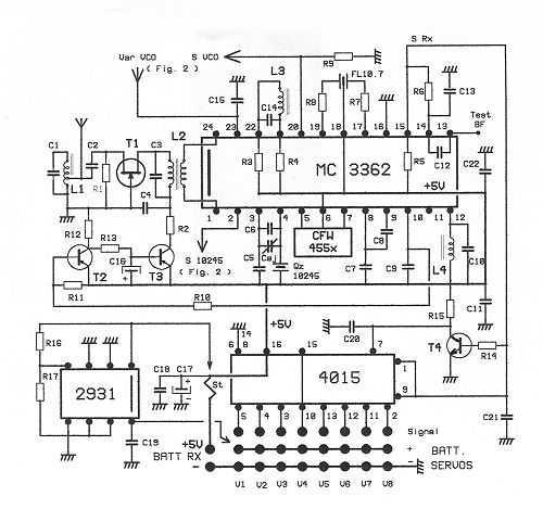
This receptor is born of our annoyance against the irritating problem of Quartz: With the RX21, completed research of cut crystal for your personal rating, you have with him, access to ALL band frequencies, in steps of 5 kHz!...
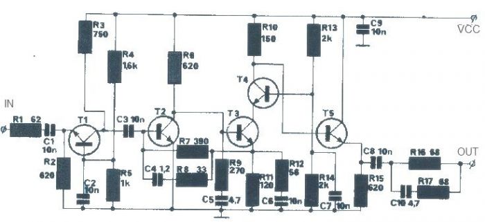
The T1 transistor must be of the BF200 type (or a similar variant), while the other transistors can be of the BF214 type. To achieve high efficiency, the antenna amplifier should be positioned at a short distance from the...
The signal EncoderBit1 (LOW) is inverted by the hex inverter U5A and then sent to a 4-input AND gate U3A, along with EncoderBit0 (HIGH), the output from a J-K flip-flop (HIGH), and a HIGH signal from Vcc. During a...
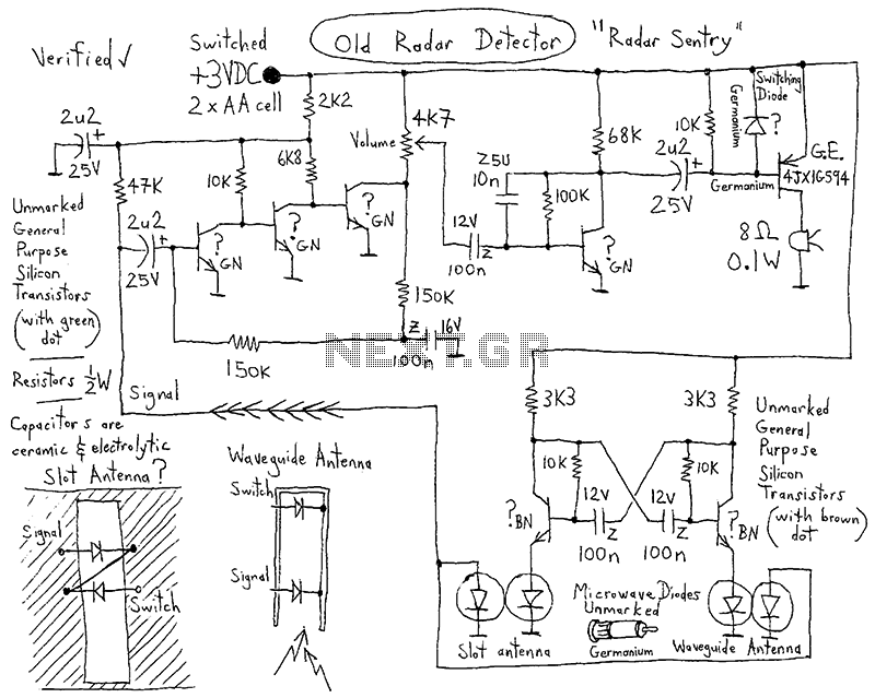
Since this is a DC circuit, how and where do the positive and negative wires physically connect to the circuit? Where exactly should all the grounds be connected? The schematic indicates the connections to the power source clearly. However,...
This project was designed to introduce a friend to microcontrollers and circuits using various functionalities and spare parts. A PS2 numpad was utilized as the key entry mechanism, which was found at a thrift store and included the necessary...