
12V to 9V 2A step down dc converter using IC 741 and 2N3055

The circuit utilizes a voltage regulator to achieve the desired output characteristics. A common choice for this application is the LM7809 voltage regulator, which is capable of providing a fixed output voltage of 9V with a maximum output current of 1A. To accommodate the requirement of 2A, a more robust solution, such as the LM317 adjustable voltage regulator or a switching regulator, may be employed.
The circuit configuration includes the following components:
1. **Input Capacitor (C1)**: A decoupling capacitor, typically rated at 1000µF, is placed at the input to filter out any high-frequency noise from the power supply. This capacitor should be rated for at least 25V to ensure it can handle the input voltage.
2. **Voltage Regulator (U1)**: The LM317 or appropriate switching regulator is used to step down the voltage from 12V to 9V. If using the LM317, external resistors will be needed to set the output voltage to 9V.
3. **Output Capacitor (C2)**: A capacitor rated at 100µF is connected at the output to stabilize the voltage and improve transient response. This capacitor should also be rated for at least 16V.
4. **Heat Sink**: If the LM317 is used, a heat sink may be necessary to dissipate heat generated during operation, especially under higher loads.
5. **Protection Diodes (D1, D2)**: Schottky diodes can be added to protect against reverse polarity and to safeguard the circuit from voltage spikes.
6. **Load**: The circuit is designed to supply a load requiring 9V at 2A. This load could be any device or circuit that operates within these voltage and current specifications.
The overall design should include considerations for thermal management, ensuring that the components operate within their specified limits, and ensuring that all connections are secure to prevent failures. Proper PCB layout techniques should also be employed to minimize inductance and resistance in the power path, which can affect performance.This circuit designs for modify power supply input 12V from battery or the other. Have the level voltage be down be left 9V be stable or , 9V at 2 Amp.. 🔗 External reference
Related Circuits
INTRODUCTION Digital to analog converters are one of the most commonly employed circuits in many applications involving digital video, signal processing, and testing. Digital to analog converters (DACs) serve a critical role in modern electronic systems by converting digital signals,...
A dimmer is not commonly found in a caravan or on a boat. This document outlines how to create one. If the goal is to adjust the ambiance while entertaining friends and acquaintances, this circuit allows for that capability....
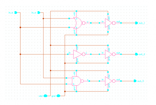
This new circuit utilizes four integrated circuits, with the option to operate with just three by combining the flip-flops and AND gates. The frequency of clock pulses dictates the revolutions per minute (RPM) of the motor. The circuit can...
A sawtooth wave oscillator circuit can be implemented using several methods. Here, one design that employs the 555 integrated circuit is presented, along with its schematic diagram. The sawtooth wave oscillator utilizing the 555 timer IC operates in astable mode,...
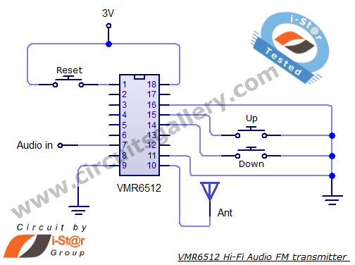
This article provides the circuit schematics for an FM transmitter along with the necessary explanations. The primary component utilized is the VMR6512 IC, a highly integrated FM audio signal transmitter chip designed for Hi-Fi audio applications. This chip can...
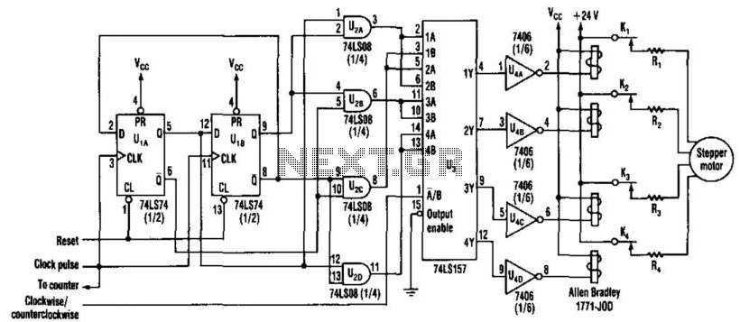
Stepper motors are a recurring subject. This circuit converts a clock signal from a square wave generator into signals with a 90-degree phase shift. Stepper motors are widely used in applications requiring precise control of angular position, speed, and acceleration....