
Stepper Motor Generator

Stepper motors are widely used in applications requiring precise control of angular position, speed, and acceleration. The circuit described facilitates the operation of a stepper motor by transforming a standard clock signal into two output signals that are phase-shifted by 90 degrees. This phase shift is crucial for driving the stepper motor in a coordinated manner, allowing for smooth and accurate stepping.
The circuit typically consists of a square wave generator, which produces a continuous square wave output. This output serves as the input to a phase-shifting network, which can be implemented using various methods, such as using operational amplifiers, RC networks, or digital logic circuits. The phase-shifting network generates two output signals: one that is in phase with the input clock signal and another that leads or lags by 90 degrees.
For example, using an operational amplifier configured as a differentiator can create a 90-degree phase shift. Alternatively, a digital circuit using flip-flops can also achieve the desired phase relationship. The resulting signals are then fed into the stepper motor driver, which interprets these signals to energize the motor coils in the correct sequence, enabling the motor to rotate in a controlled manner.
Proper design considerations for this circuit include ensuring the frequency of the clock signal is suitable for the stepper motor being used, as well as accounting for the required current and voltage levels to drive the motor coils effectively. Additionally, the circuit may include features such as adjustable frequency control to allow for variations in motor speed and performance.Stepper motors are a subject that keeps recurring. This little circuit changes a clock signal (from a square wave generator) into signals with a 90-degree.. 🔗 External reference
Related Circuits
Two stepper motors are to be controlled by a dsPIC microcontroller. The programming of the microcontroller has been completed, but there is confusion regarding the use of the L298 driver. Assistance is needed with the circuit design. To control two...
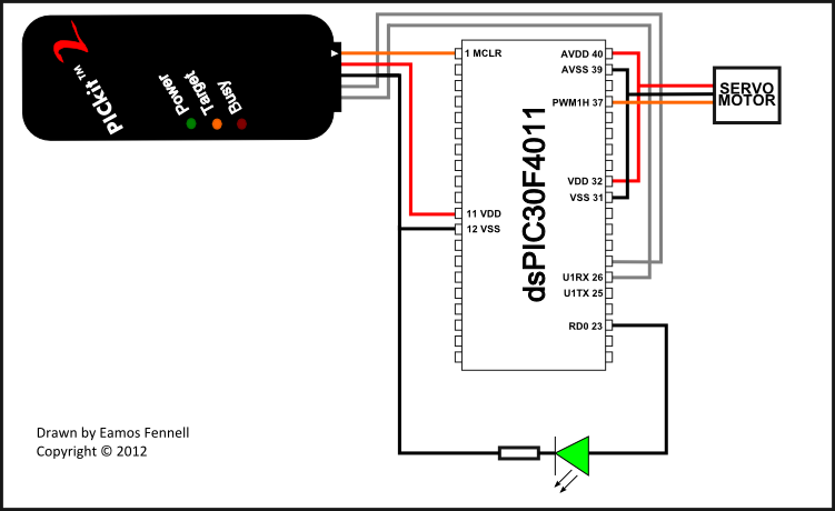
A servo motor is a compact device that consists of a three-wire DC motor, a gear train, a potentiometer, an integrated circuit, and an output shaft bearing. The three wires extending from the motor casing include one for power,...

By utilizing a 556 dual timer, with IC1A functioning as a waveshaper and IC1B as a pulse generator, a pulse width range of 10:1 can be achieved. This circuit can be triggered using a sine wave. The circuit operates on...

If the control circuit of this motor driver is based on a microcontroller or digital component, it is advisable to implement a buffer for each port that controls the stepper motor driver. This precaution helps prevent overloading the microcontroller...
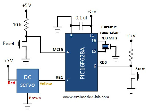
A servo motor is a specialized geared DC motor that includes an electronic circuit for controlling the direction and position of the motor shaft. Due to its capability for precise angular positioning, servo motors are widely utilized in robotics,...
PWM waveforms are widely utilized to regulate the speed of DC motors. The duty cycle of the digital waveform can be established either through an adjustable analog voltage level (as seen in a NE555-based PWM generator) or through digital...