
Simple FM Transmitter circuit schematic Long range short range using VMR6512 Hi-Fi Audio FM transmitter module

The VMR6512 FM transmitter circuit is designed for versatility in audio transmission applications. The integration of a DSP within the chip allows for complex audio processing, ensuring high fidelity in sound reproduction. The matching network facilitates impedance matching, which is critical for efficient RF transmission, minimizing signal loss and ensuring that the maximum amount of power is radiated by the antenna.
The reset functionality is essential for initializing the transmitter's operation, allowing it to start at a predetermined frequency and power level, which is crucial for maintaining consistent performance across various applications. The analog input pins are designed to accept audio signals directly from a pre-amplifier, making the design compact and efficient.
The digital audio input interface is particularly noteworthy as it supports multiple formats, providing flexibility in integration with various audio sources. The UP and DOWN control pins for frequency adjustment allow for real-time tuning of the transmitter, which is beneficial in dynamic operating environments where interference may occur.
For the antenna, the recommendation of a 1/4 wavelength design is based on its effectiveness in radiating RF energy efficiently and ensuring a good match with the transmitter's output. This design choice enhances the overall range and clarity of the transmitted audio signal, making the VMR6512 FM transmitter suitable for a wide range of applications from personal use to professional broadcasting.This article gives the FM transmitter circuit schematics with necessary explanation. The main component used here is the VMR6512 IC which is a highly integrated FM audio signal (Hi-Fi Audio FM) transmitter chip. You can use this as FM radio transmitter for different applications such as FM transmitter for car, digital FM transmitter, Hi-Fi wireles
s headphone, Conference Broadcasting System, accessories of audio-visual entertainment equipment and radio station in campus. This wireless audio transmitter chip integrates superior digital signal processor (DSP), matching network, frequency synthesizer and RF power amplifier.
So it can grasp FM audio modulation without any external components. You need a pre amplifier section in order to transmit our voice directly as FM. Refer my condenser mic pre amplifier circuit. Related article: Most simple FM transmitter circuit diagram Reset pin set to high PWL will reset the controller, DSP and frequency synthesizer. After reset, the communication frequency will be100. 0MHz and the power will be 115dBuV. The system begins working 160ms once the Reset signal becomes lower. Analog audio input Rin, Lin Rin and Lin is the analog audio input pin of VMR6512 module. There is a capacitor in the pin. So the other exterior components are not needed. Audio input impedance is approximately 56 k ©. Digital audio input interface consists of SCLK, DIN and FS. It can be set to I2S, DSP and Left Justified three different formats through commanding and connected without a glitch with almost all the DSP.
UP and DOWN pins are used to modify the operating frequency exclusive of the external controller. Each low PWL impulse larger than 0. 05 seconds of UP / DOWN pin will make output RF power raise or decrease 0. 1MHz. If you stay low PWL, then the operating frequency will change continuously every 0. 3 seconds. As the unit has internal matching networks, RF output signal pin should be directly connected to the line without any components. It is proposed that antenna should use 1/4 wavelength wire or rod antenna. 🔗 External reference
Related Circuits
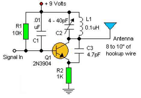
This basic RF oscillator circuit is easy to build and the components are not critical. Most of them can be found in your junk parts box. The L1 antenna coil can be made by close winding 8 to 10...
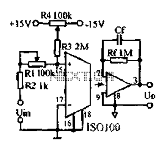
An adjustable gain test is conducted in preparation for an isolation amplifier circuit, utilizing the optical coupling isolation amplifier ISO100. This adjustable gain can form part of a test device for the isolation amplifier. The circuit gain can be...
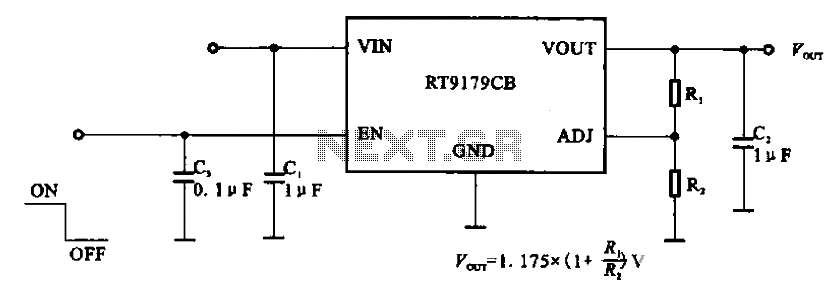
The RT9179CB is a power management chip utilized in power supply circuits. It serves as a linear regulator power management chip. This circuit is commonly employed in various products, such as computer motherboards, LCD monitors, and others. It is...
Men, in particular, appreciate the convenience of television remote controls, which can often lead to frustration for their female partners. Men seem to have a desire to understand what... The initial statement highlights a common dynamic in household technology usage,...
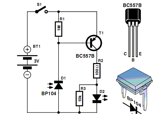
Instructions for creating a Clap-Clap On/Clap-Clap Off switch circuit. This guide provides the necessary information for constructing a clap-activated switch. The Clap-Clap switch circuit is an innovative design that utilizes sound activation to control electronic devices. The primary components of...
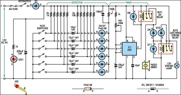
This simple alarm circuit is designed for use in a combined garage and rumpus room. It can be assembled on Veroboard and utilizes a single integrated circuit (IC) along with a few inexpensive components. The circuit is based on...