
12VDC to 230VAC 60W Inverter Circuit

The described inverter circuit employs a multivibrator configuration using two BC548 transistors (T1 and T2) to generate a square wave signal at a frequency of 50Hz. This frequency is crucial for the inverter's operation, and the resistors R3 and R4 play a significant role in determining the oscillation frequency. After initial testing, these resistor values may need to be fine-tuned to ensure optimal performance.
The output from the collectors of T1 and T2 is fed into two Darlington pairs formed by transistors T3-T4 and T6-T7, which are BD140 and 2N6107, respectively. The Darlington configuration provides high current gain, which is essential for driving the larger power transistors (T5 and T8). The 2N3055 transistors are configured in a push-pull arrangement, allowing the inverter to efficiently convert the DC voltage from the battery to an AC output suitable for driving loads.
To enhance the output capability of the inverter, the drive to the 2N3055 transistors can be increased. This can be achieved by lowering the resistance values of R7 and R8, which would allow more base current to flow into T5 and T8. However, it is important to ensure that these resistors can handle the increased power dissipation, necessitating the use of higher wattage ratings.
Thermal management is a critical aspect of the design, as the output transistors can generate significant heat during operation. Therefore, suitable heat sinks should be attached to the 2N3055 transistors to maintain their operating temperature within safe limits, thus preventing thermal runaway and ensuring reliability.
The transformer (X1) is a key component, with a primary winding rated for 230V and a secondary winding of 9V-0-9V at 10A. This transformer is used in reverse to step up the voltage from the inverter's output to the desired AC voltage level. The design effectively utilizes the transformer to provide isolation and voltage transformation, making it suitable for various applications where a stable AC supply is required from a DC source. Overall, this inverter circuit presents a practical solution for powering medium loads efficiently and economically.The following circuit is a cheap completely transistorised inverter circuit ideal for driving medium loads with the order of 40 to 60 watts working with battery of 12V, 15 Ah or larger power capacity. Transistors T1 and T2 (BC548) make a 50Hz multivibrator. For having right frequency, the values of resistors R3 and R4 might need to be modified aft er testing. The complementary outputs from Collectors of transistors T1 and T2 are provided to PNP darlington driver phases created by transistor pairs T3-T4 and T6-T7 (utilising transistors BD140 and 2N6107). The outputs from the drivers are fed to transistors T5 and T8 (2N3055) connected for push-pull operation.
Somewhat bigger wattage can be accomplished by growing the drive to 2N3055 transistors (by lowering the value of resistors R7 and R8 while raising their wattage). Suitable heatsinks may be applied for the output stage transistors to keep the transistor from overheating.
Transformer X1 is really a 230V primary to 9V-0-9V, 10A secondary used in reverse. 🔗 External reference
Related Circuits
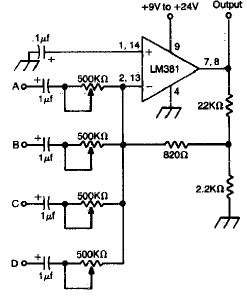
LM381 4-channel audio mixer circuit design project using a few common electronic parts. The LM381 audio mixer circuit is designed to combine audio signals from four separate channels into a single output. This circuit employs the LM381 integrated circuit, which...
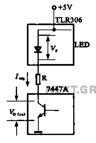
The circuit depicted is a large high-brightness LED driver designed to provide sufficient drive current, utilizing integrated circuits such as the 7447A or 74247. The digital display tube consists of eight light-emitting diodes, with seven dedicated to the digital...
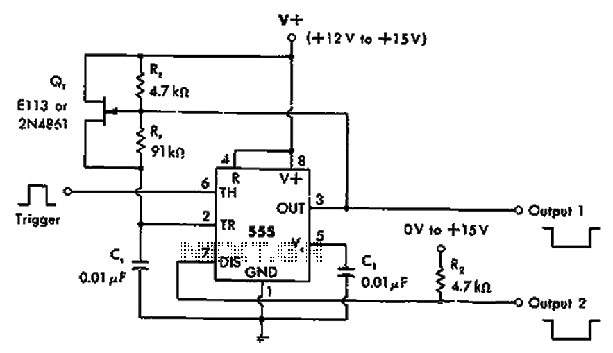
The timer 555 is activated by a positive trigger pulse, which results in negative output pulses. In scenarios where the duty cycle exceeds 99%, heavy loads can be disconnected from pin 7 without impacting timing accuracy, although loads exceeding...
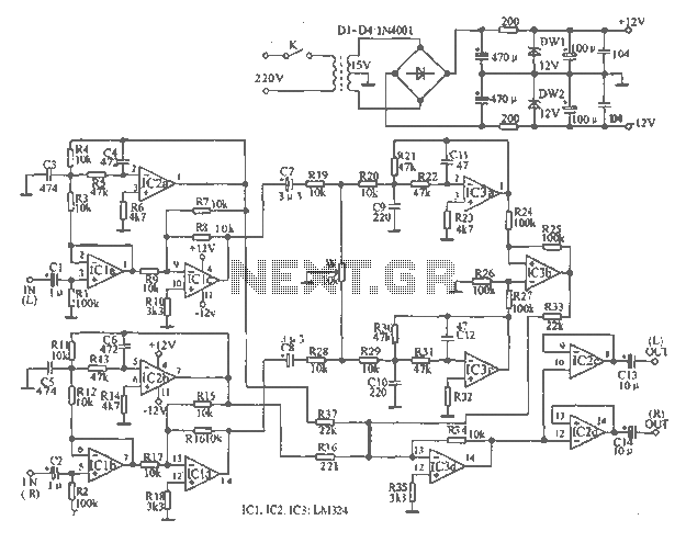
The tape output circuit processes the left and right channel signals through a first buffer amplifier. The output signal is split into two paths: one route directly connects to an amplifier for amplification, while the other route passes through...
Writing about multiple circuits in Marx, an entire new set has been discovered, referred to as "the" Marx Generator. There are diagrams available, along with a useful quote: "The main advantage of the Marx circuit configuration over a more...
A very regular configuration of the 555 astable timer to work as a timer to trigger an alarm or any other equipment connected to pin 3. R resistor should be replaced with a potentiometer that will change the time...