
Time delay circuit (555)
")
The 555 timer in astable mode is widely utilized for generating square wave signals and timing applications. In this configuration, the 555 timer operates continuously, switching between its high and low states, thus creating a pulse output on pin 3. The frequency and duty cycle of the output waveform depend on the values of the resistors and capacitor connected to the timer.
In a typical setup, two resistors (R1 and R2) and one capacitor (C) are connected to the 555 timer. The output frequency (f) and the duty cycle (D) can be calculated using the following formulas:
- Frequency (f) = 1.44 / ((R1 + 2 * R2) * C)
- Duty Cycle (D) = (R2 / (R1 + 2 * R2)) * 100%
In this configuration, R1 is connected between VCC and pin 7 (discharge), while R2 connects pin 7 to pin 6 (threshold) and pin 2 (trigger). The capacitor C is connected from pin 6 to ground. To allow for adjustable timing, R1 can be replaced with a potentiometer, enabling the user to vary the resistance and thus alter the timing interval effectively.
The capacitor C must be selected based on the desired timing characteristics. It is essential to calculate its value using online 555 timer calculators, which can provide precise values based on the chosen resistances and the required frequency.
While this design is straightforward and effective for many applications, it may lack precision due to component tolerances and temperature variations. Nevertheless, its simplicity and ease of implementation make it a popular choice for triggering alarms, LED flashers, and other timing-related tasks in everyday electronics.
The output from pin 3 can drive various loads directly or via a transistor for higher current applications, making this configuration versatile for different electronic projects.A very regular configuration of the 555 astable timer to work as a timer to trigger an alarm or any other equipment connected to pin 3. R resistor should be replaced with a potentiometer that will change the time delay. Capacitor C should be calculated too (there are many 555 calculators around internet).Is a common design, not very accurate but very usefull in many everyday aplications.
🔗 External reference
Related Circuits
A DC motor reversing circuit using non-latching push button switches. Relays control forward, stop, and reverse action, and the motor cannot be switched from forward to reverse unless the stop switch is pressed first. The described circuit employs a system...
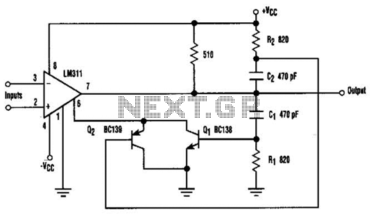
When the comparator's output transitions from low to high, the rising edge of the output pulse, differentiated by the Cl/Rl chain, activates Ql. This action blocks the comparator via its strobing input and maintains its output state for a...
%2BCircuit%2Bdiagram%2Busing%2BCD4047%2Band%2BIRFZ44%2Bpower%2BMOSFET.png)
This simple low-power DC to AC inverter circuit converts 12V DC to either 230V or 110V AC. By making simple modifications, it is also possible to convert 6V DC to 230V AC or 110V AC. This inverter can be...
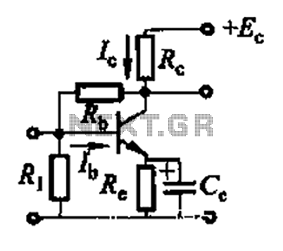
Basic reference transistor bias circuit - Mixed Negative feedback The basic reference transistor bias circuit utilizing mixed negative feedback is a fundamental electronic configuration designed to stabilize the operating point of a transistor. This circuit typically employs a combination of...

Lithium-based (Li+) batteries are increasingly used in portable devices due to their favorable characteristics. However, they are often in limited supply, leading to long lead times unless a preferred-customer status is established with manufacturers. Consequently, a backup alternative to...
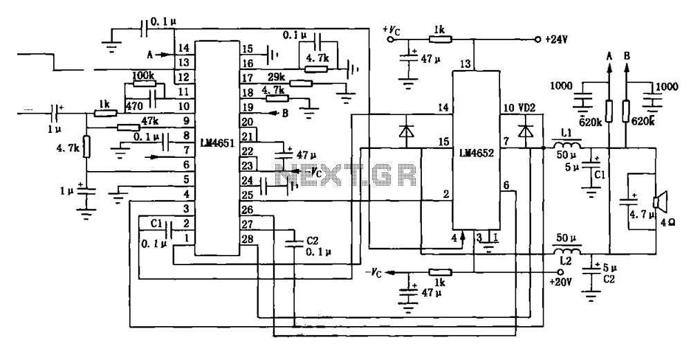
Figure (a) illustrates a 170W output amplifier circuit designed for a 4-ohm load. The LM4651 is a class D amplifier presented in a 28-pin DIP package, with its internal equivalent circuit depicted in Figure (c). The 170W output amplifier circuit...