
1300 Mhz Frequency meter with prescaler

The project involves the construction of a frequency counter utilizing the U664B prescaler chip, which is capable of dividing input frequencies from 30 MHz to 1300 MHz by a factor of 64. This allows the circuit to handle a wide range of frequencies effectively. The choice of the PIC16F84 microcontroller serves as the core processing unit, providing the necessary control and measurement capabilities.
The U664B prescaler functions by taking an incoming high-frequency signal and reducing its frequency by the specified division factor. This is crucial for accurate frequency measurement, as the microcontroller can only process lower frequency signals. The compatibility of the U664B with the SAB6456 prescaler allows for a straightforward integration into existing designs, as the pin configurations are identical.
In adapting the original project by Peter Halicky, modifications were made to the firmware to accommodate the U664B's division factor and the different crystal oscillator frequency. The original design utilized a 10 MHz crystal oscillator, while this implementation employs a 4.8 MHz crystal oscillator. The code adjustments ensure that the timing and gating intervals are correctly calibrated for the new operating frequencies, which is essential for maintaining measurement accuracy.
The overall architecture of the circuit involves the prescaler connected to the input frequency source, followed by the microcontroller that processes the divided signal. The microcontroller's firmware is programmed to handle the counting of pulses over a specified gating period, allowing for the display of the corresponding frequency. The output can be interfaced with a display module to present the measured frequency in a user-friendly format.
This frequency counter design is suitable for various applications, including amateur radio, electronics testing, and educational purposes, providing a practical tool for frequency measurement across a broad spectrum of signals.Having found an u664b prescaler chip (Telefunken) from an old tv-tuner , I decided to build a valid frequency counter using pic16f84 , the prescaler I use is able to divide by 64 every frequency from 30 to 1300 MHZ. The original project is from Peter Halicky but as he used a sab6456 prescaler (divider by 256) I had to change the code to adjust the gating time to my different divider factor ( 64) and also to my 4.8 MHZ xtal (he use 10 MHz xtal). However the U664b is perfectly compatible to SAB6456 so you can substitute it pin to pin. The measuring is divided in 🔗 External reference
Related Circuits
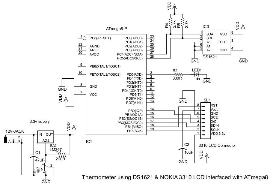
This document presents an application utilizing the Nokia 3310 LCD for designing a thermometer using the DS1621 temperature sensor IC. The DS1621 is an 8-pin sensor manufactured by Maxim. The circuit design involves integrating the DS1621 temperature sensor with a...
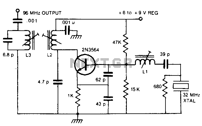
By utilizing a crystal oscillator operating between 27 and 33 MHz, the third harmonic frequency will produce an output ranging from 82 to 99 MHz. The implementation of a crystal oscillator within the specified frequency range of 27 to 33...
This design circuit is used to activate circuitry and an analog meter for sensitive DC current measurements. A subsequent inquiry raised the possibility of measuring AC microamperes, which inspired the idea for this circuit. The circuit is designed to facilitate...

The LM2917 IC chip is specifically designed as a Frequency to Voltage Converter. Its applications as a Frequency to Voltage Converter require few external components. The LM2917 datasheet includes several examples of its applications. The advantages of the single-chip...
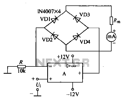
An operational amplifier, a diode bridge rectifier, and DC mA AC voltmeter tables are illustrated in the figure. The operational amplifier used is the LM324. The measured AC voltage is applied to the inverting terminal of the operational amplifier,...

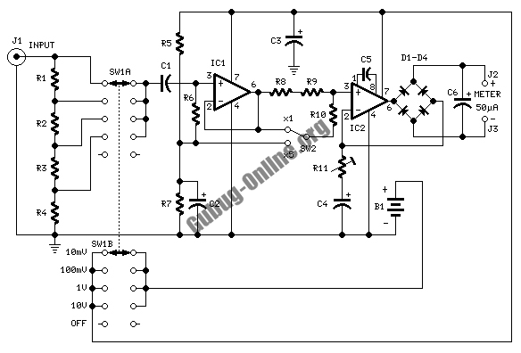
Construct a digital multimeter capable of measuring DC and AC voltages up to 100V and DC and AC currents up to 1A. The circuit will be powered by a 9V battery. The design incorporates a modified voltmeter to suit...