
144mhz 2m converter

The circuit design incorporates a frequency conversion method that allows for the reception of VHF signals in the 2-meter band. The use of a converter with an RF amplifier and a crystal-controlled oscillator enhances the overall performance by ensuring stability and sensitivity. The choice of inductors and transformers is critical, as they shape the frequency response and tuning capabilities of the circuit. The layout emphasizes minimizing connection lengths to reduce signal loss and interference, which is particularly important in VHF applications. Proper tuning of the various components is essential to achieve optimal performance, and the use of tools such as signal generators and absorption frequency indicators can facilitate precise adjustments. The housing of the converter in a closed aluminum box not only protects the components but also helps in shielding against external electromagnetic interference. The selection of appropriate transistors and FETs is vital for achieving reliable oscillation and amplification, ensuring that the receiver can effectively process the converted signals. Overall, this design provides a robust solution for receiving 2-meter VHF signals, balancing complexity and performance for effective communication applications.The reception of 2 metre signals is generally with a converter and short wave receiver, preferably of communications type. The latter will have sensitivity and selectivity better than average. With such an arrangement of equipment, the 144MHz or other VHF signal is changed in frequency so that the converter output falls within the tuning range of
the receiver. A converter of this type often has its own RF amplifier, and a relatively low frequency crystal controlled oscillator, followed by frequency multipliers. This allows high sensitivity and excellent frequency stability, but is a relatively complicated and expensive item.
Bearing in mind that at this frequency the RF amplifier will not, contribute very much gain, and that tunable VHF oscillators L1 is broadly tuned to the wanted frequency band by T1, and signal input is to gate 1 of TR1. TR2 is the local oscillator, and the operating frequency here is determined by L2 and T2. Oscillator injection is via C3 to gate 2 of TR1. The frequency of the output from the drain of the mixer TR1 is the difference between G1 and G2 frequencies.
Thus if the signal at G1 is 144MHz, and TR2 is tuned to oscillate at 116MHz, output will be at 144 minus 116MHz, or 28MHz. Similarly, with the oscillator set at 116MHz, an input at 146MHz to G1 will give an output of 30MHz. Therefore 144-146MHz can be covered by tuning the receiver from 28MHz to 30MHz. L3 is broadly tuned to this band, and L4 couples the signal to the short wave receiver. The oscillator can actually be tuned above or below the aerial circuit frequency of the converter, as it is the difference between converter signal input and oscillator frequencies which determines the converter output frequency.
It is also possible to choose other reception and output frequencies, provided L1, L2 and L3 are chosen to suit. L1 and L2 are wound in the same way, except that L1 is tapped one turn from its grounded end. Each coil has five turns of 18swg wire, self supporting, formed by winding the turns on an object 7mm in diameter.
Space turns so that each coil is ½in or about 12mm long. L3 is fifteen turns of 26swg enamelled wire, side by side on a 7mm former with adjustable core. L4 is four turns, overwound on the earthed (positive line) end of L3. Layout should allow very short connections in the VHF circuits. A co-axial aerial socket is fitted near L1. A screened coaxial lead is preferred from L4 to the receiver, to avoid unnecessary pick-up of signals in, the 28-30MHz range. The converter will operate from a 9v to 12v supply. L3 should first be peaked at about 29MHz. If a signal generatoris available (that described later can be used) couple this to TR1 drain by placing the output lead near the drain circuit.
Tune generator and receiver to 29MHz, and adjust the core of L3 for best results. Otherwise, couple an aerial by means of a small capacitor to the drain circuit, and tune in some signal in the 28- 30MHz range, to allow adjustment of the core of L3. It is now necessary to tune L1 to about 145MHz, and L2 to 116MHz, or 174MHz. If an absorption frequency indicator is available, this will permit an approximate setting of T2. A dip oscillator will also allow T1 to be adjusted. (The circuits shown later may be used here. ) Subsequently adjust L2 to bring the wanted signals in at the required frequencies on the receiver, and peak these for best volume with T1, and check the setting of L2 core.
The converter is best assembled in a small aluminium box, completely closed, which can be placed behind the receiver. Note that if TR2 is not oscillating, no reception is possible through the converter. TR2 should be a VHF FET, such as the BF244, MPF102, and similar types, and if necessary T3 may be adjusted to secure oscillation here.
The 40602, 40673, and similar VHF types will be satisfactory for TR1. If needed, frequencies can be brought within the swing of T1 and T2 by stretching or compressing L1 or L2. 🔗 External reference
Related Circuits
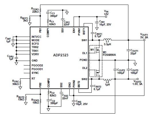
The ADP2323 DC-DC converter is designed to deliver two output voltages with specified maximum output currents. The first channel provides a 5-volt output with a maximum current of 2 Amperes, while the second channel supplies 1 volt with a...
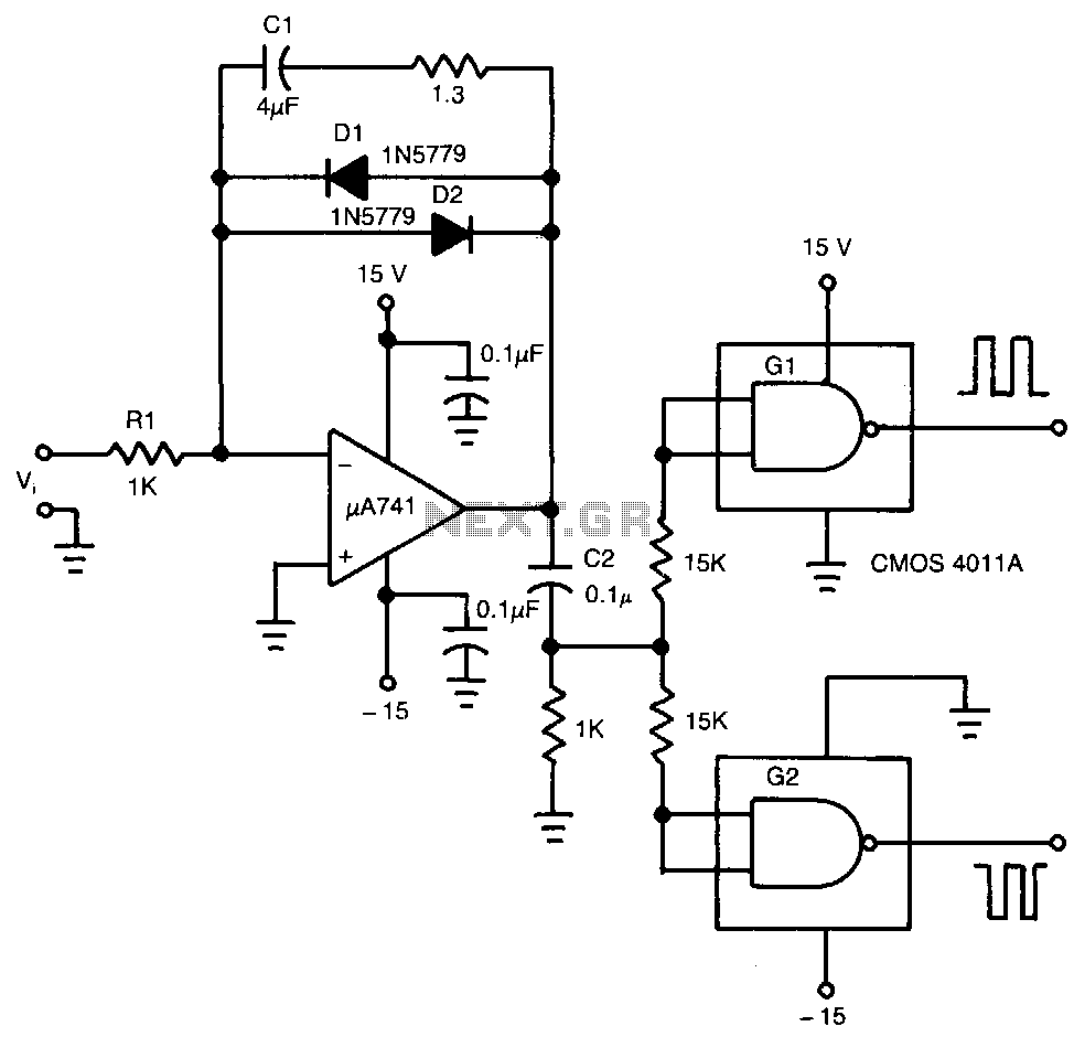
The input voltage, V1, causes capacitor C1 to charge, producing a ramp voltage at the output of the 741 operational amplifier. Diodes D1 and D2 are four-layer devices. When the voltage across C1 reaches the breakover voltage of either...
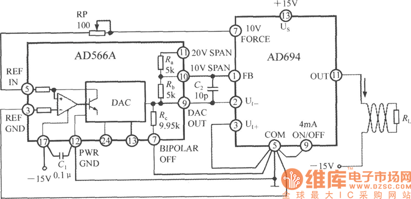
The current loop interface circuit diagram of the AD694 multi-functional sensor signal conditioner is utilized as a digital-to-analog converter (DAC). This current loop interface enables the conversion of digital values into voltage and subsequently into current signals. The circuit...
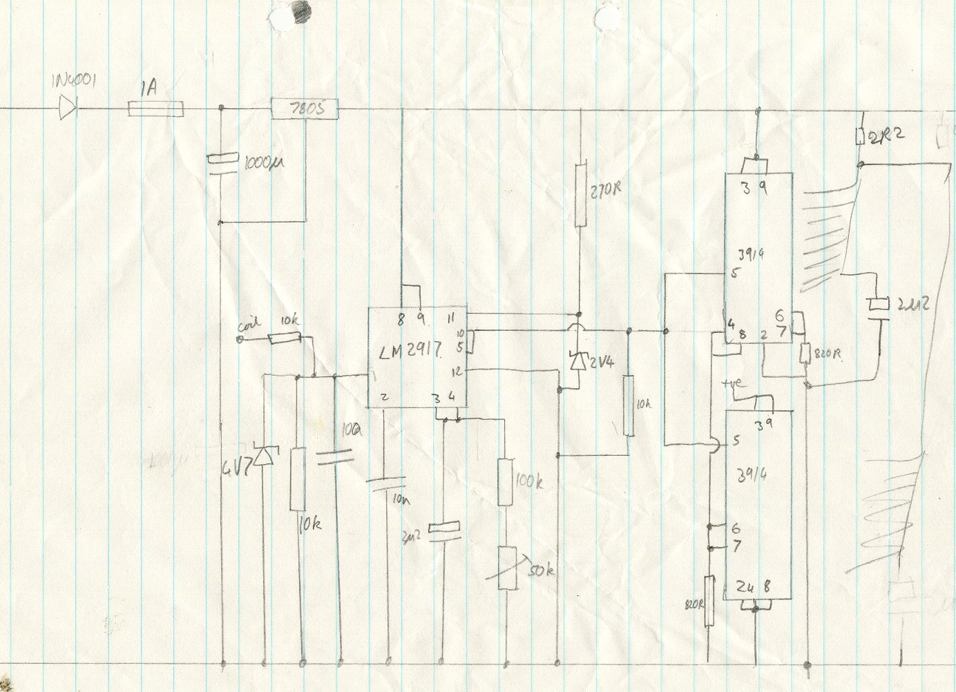
This circuit utilizes an LM2917 frequency-to-voltage converter. The input is connected to the low voltage side of the ignition coil, with various components designed to produce a full-scale output at 6000 RPM, corresponding to 12000 ignition pulses per minute,...
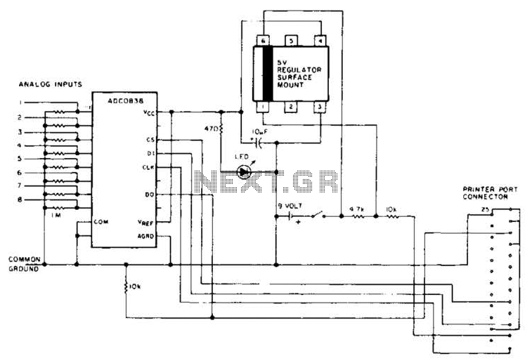
An A/D converter by National Semiconductor (ADC0838) converts 0 to 5 V analog inputs into a digital data format. A 9 V battery is utilized. The converter connects to the pointer port connector through a 25-pin connector. The ADC0838 is...
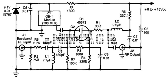
This converter utilizes a 40673 MOSFET to heterodyne the 5.5 to 8 MHz TVRO subcarriers to the FM broadcast band, enabling the use of a stereo receiver for high-fidelity stereo reception of TV sound subcarriers. Z1 is a prepackaged...