
LM2917 frequency to voltage converter

This circuit design employs the LM2917 frequency-to-voltage converter, which effectively translates the frequency of ignition pulses from the ignition coil into a proportional voltage output. The connection to the low voltage side of the ignition coil ensures accurate readings of engine RPM by capturing the frequency of the ignition events. The design aims for a full-scale output at 6000 RPM, which translates to 12000 pulses per minute, resulting in a frequency of 200 Hz.
The voltage output from the LM2917 is directed to two LM3914 bar graph drivers, which are configured to visually represent the engine RPM through a series of LEDs. The choice of using two red LEDs for the top segments serves to indicate critical RPM thresholds, while three orange LEDs provide a transitional warning zone. The remaining green LEDs indicate normal operating conditions. The design incorporates a deliberate transition point between the two bar graph drivers at 3000-3300 RPM, which is strategically aligned with the engine's optimal performance range. This not only enhances the usability of the display but also allows for immediate visual feedback to the operator regarding engine performance.
The PCB design process involved etching techniques, utilizing transfer methods for pad placement and manual pen tracing for circuit pathways. This approach ensures precision in the layout, while the drilling of holes for components was executed with a modified paperclip, demonstrating a resourceful method for achieving necessary component placements. Soldering was performed with a small hand drill, indicating a hands-on, practical approach to the assembly of the circuit. Overall, this circuit design provides a reliable and effective means of monitoring engine RPM through visual indicators, enhancing the operational efficiency of the engine.This circuit uses an LM2917 frequency to voltage converter. The input was connected to the low voltage side of the ignition coil, and the various components around it design to produce a full scale output at 6000rpm, which corresponds to 12000 ignition pulses per minute, or 200Hz. The voltage from this was then fed to 2 cascaded LM3914 bargraph dr ivers. I had 2 red LEDs for the top two segments, then 3 orange leds, and the rest were green. The "join" between two bargraph drivers was at 3000-3300rpm, which corresponded closely with the point at which the engine started to work well, so I set up the right-hand LEDs slightly brighter than the left hand ones. I etched a PCB (ahh the quality of the documentation!), using transfers for the pads and a pen for the lines, drilled the holes (with a snipped off paperclip for a drill bit) with a small plastic handdrill, and got soldering.
🔗 External reference
Related Circuits
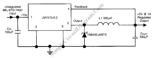
This is a 28VDC to 5VDC switching converter circuit. As a switch-mode voltage regulator, this circuit provides higher efficiency than linear regulator types. The 28VDC to 5VDC switching converter circuit operates by converting a higher voltage direct current (DC) input...
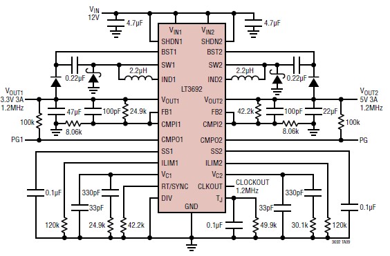
The LT3692 dual current mode PWM step-down DC-DC converter circuit, featuring two internal 3.5A switches, can be designed into a simple power supply circuit suitable for various electronic applications, such as distributed supply regulation or automotive circuits. The LT3692...
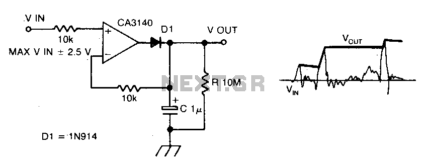
The circuit employs negative feedback exclusively for positive signals. The inverting input receives feedback only when diode D1 is forward biased, which occurs solely with positive input signals. As the positive input signal increases, the output of the operational...
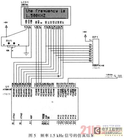
The primary function of the frequency counter is to measure the frequency and cycle of a signal. Its applications span a wide range, extending beyond simple instrument measurements to areas such as education, scientific research, high-precision instrument measurement, and...
After conducting some research, it was found that voltage can be adjusted using either a voltage regulator chip or resistors. Several scenarios require reducing the voltage for motors, prompting a question about the appropriate method for each application. An...
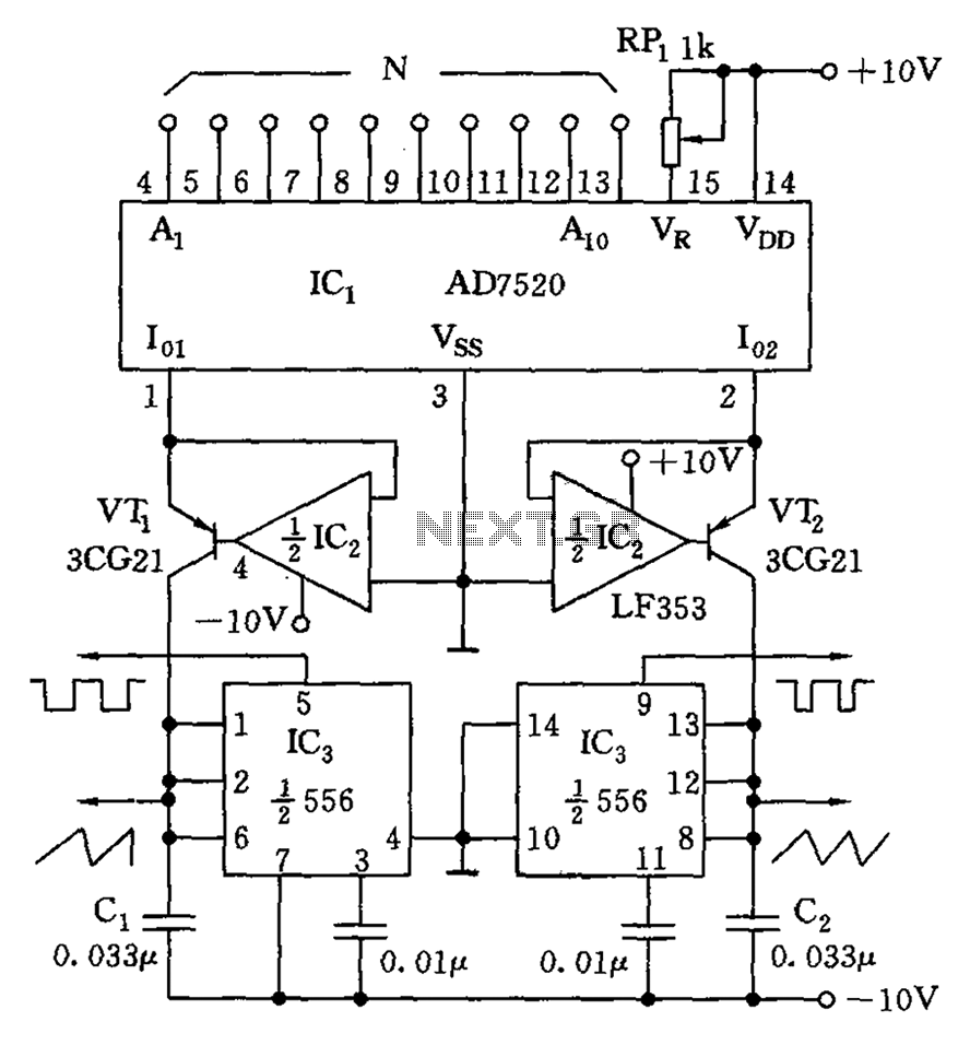
As shown in the figure, the AD7520 is a CMOS type integrated circuit Digital-to-Analog Converter (DAC) featuring 10 channels. It can provide 10 N-bit digital outputs that are proportional to the input current Io1, as well as outputs that...