
15 x 7 LED display with PIC16F628

The circuit utilizes a PIC16F628 microcontroller and a 4017 decade counter to drive a matrix of 105 LEDs organized in a 15x7 configuration. The microcontroller's output ports (Port A and Port B) are employed to manage the LED rows and columns, with Port A controlling 7 rows and Port B managing 8 columns. The LEDs are activated in a time-multiplexed manner, where each row is illuminated sequentially for a brief duration, effectively creating the illusion of a continuously lit display due to the persistence of vision.
The 4017 decade counter is essential for sequencing the LED activation, cycling through its outputs to determine which row is currently active. This is achieved by connecting the counter's output pins to the base of driver transistors that control the current to the LEDs. Each LED has a series resistor (82Ω) to limit the current to approximately 30mA, ensuring safe operation while maximizing brightness.
To maintain synchronization between the PIC microcontroller and the 4017, a synchronization routine is executed at startup, establishing the initial state of the counter and the microcontroller. This is crucial for accurate LED scanning, as any desynchronization could lead to incorrect LED illumination.
The design emphasizes the use of surface-mount technology, allowing for a compact circuit layout on a matrix board. While the current prototype is built on a matrix board, the final version is intended to be fabricated on a double-sided PCB with plated-through holes to accommodate the LED matrix and other components more securely.
The project is well-suited for various applications, including advertising displays and information boards, demonstrating the versatility of LED technology combined with microcontroller control. The careful consideration of current management and synchronization ensures a reliable and visually appealing output.This project is provided as a "prototyping project" as no PC board has been produced. The photographs show the project built on a matrix board using surface-mount components and very fine wire. The final design will require a double-sided board with plate-through holes, especially for the matrix of LEDs, but for the moment you can refer to the photographs and construct the circuit yourself.
Don't be put off by the appearance of the circuit. It is really just a duplication of a very simple circuit driving a LED that can be built on a matrix board with 0.1" spacing. Most of the surface-mount components can be positioned so the legs will reach a solder-land and you won't need a special surface-mount board.
The voltage on the PIC chip is critical and the author had some random faults develop on the screen when the voltage dropped below 4.5v. As soon as any unusual fault develops, the first thing to do is check (replace) the batteries. The author also had a problem with the PIC chip when the supply was above 5.6v (in another project). The circuit looks very complex but it consists of just two chips, 105 LEDs, a set of driver (buffer) transistors and 6 tactile switches.
All the transistors and resistors seem to disappear when surface-mount components are used and the whole project can be constructed on matrix board or on a double-sided plate-through hole PC board. The 4017 is a "decade counter" and this means it has 10 outputs, starting with output pin 3, only one output is HIGH at a time.
The 10th output is pin 11 and then the counter starts at pin 3. The program starts by clocking the 4017 until pin 9 is HIGH. This pin is connected to the input of the PIC chip and the program now knows the state of the 4017. This is called SYNCHRONISING. See more on this below. The '628 has two ports, Port A and Port B. Port A has 7 output lines (plus one input-only line) and Port B has 8 output lines. This creates our 15 lines for the screen. The screen is laid out as 15 LEDs "across" and 7 LEDs "down." The data (or information) is fed in at the top of the screen from the PIC chip to the 15 LEDs and the LEDs are connected to the 0v rail via a transistor that is driven from the 4107 chip. Each LED has an 82R resistor in series with the drive-line from the PIC chip and when you work out the voltage available and the value of the series resistance, you will find the current is about 30mA.
Since there are 7 rows of LEDs, each row is only turned on for 1/7th of the total time and this is why you need to drive the LEDs with a high current, as they are only getting a pulse for a very short period of time. Pulsing the LEDs like this produces a much brighter result than a constant current as your eye has a delay (or an extension) in seeing the illumination - called PERSISTENCE OF VISION and the end result is a very bright screen.
The top row is turned on for a short period of time as determined by a delay routine and then the drive-lines are turned off. The information for the next line is then placed on the drive-line (port A and B) and the outputted to the screen.
This also clocks the 4017 so the second row of LEDs is illuminated. The program does not know which row of LEDs is being illuminated during the scanning process and that is why it is necessary to synchronize the two chips when the project is turned on, via a short sub-routine. For the remainder of the running, the program assumes the two chips remain in synchronization. There is no reason why this will not be maintained, but it is not checked or verified at any stage. More on this under "SYNCHRONISING " below. This project uses 105 LEDs to produce a screen 15 LEDs long, by 7 LEDs High for "Running Messages." This is one of the best projects you can build as it has the widest application - - in shops, outdoor advertising, roadside information and lots more - larger signs are just an extension of the technology you learn in this project.
Larger displays can show more letters but this is the largest display that can be produced with a single PIC16F628 micro. The LEDs are scanned by turning on the 15 LEDs along the top row from the PIC micro and sinking them via a transistor connected to the 4017 chip.
Each of the 15 LEDs is buffered by a transistor so the brightness of the screen can be a maximum. After the 7 rows of LEDs, the 4017 accesses the 5 switches and the scan repeats. By keeping the scan-rate high, no flicker is detected and the whole screen can be illuminated to a very high intensity as high-brightness LEDs are used. When-ever you create a project as complex as this, there are a lot of things you have to decide upon and "invent." After deciding on the direction-of-scan, the letters and numbers have to be created and placed in a table.
The table (or tables) cannot be longer than a total of 256 bytes for all the tables as it is very awkward to access the second page of memory. The first page is actually called "page 0" and occupies program memory from 000 to 0FFh. You will notice we have only put two instructions before the tables, so they can be maximum length. The next clever feature of the program is detecting the end of each character. Instead of placing a "marker" such as 0FFh, we have incorporated the marker with the last column (last byte) of data.
Refer to the following image showing the letters A to Z and see the last value for each column is increased by a value of 08h. This assumption is not allowed in an emergency environment but is perfectly suitable in our case. 🔗 External reference
Related Circuits
This electronic clock comprises the LM8365 and the LDD640R displays. The LM8365 can show the hour/minute and month/day. Users can set two alarm outputs, AD1 and AD2, by pressing either the 12h or 24h button. The operating voltage range...

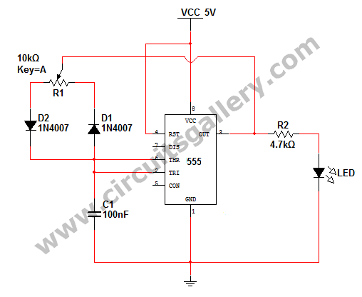
The circuit illustrated briefly flashes an LED to attract attention and remains illuminated as long as power is supplied. The circuit utilizes the well-known 555 timer integrated circuit (IC) configured as a standard astable multivibrator with resistors RA, RB,...
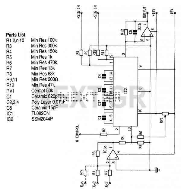
This circuit utilizes the SSM2044 integrated circuit (IC), which is a four-pole voltage-controlled filter specifically designed for electronic music applications. The on-chip voltage control of resonance facilitates straightforward interfacing with programmers and controllers. The IC is characterized by an...
How to change the brightness of an LED. Are LED lights dimmable? Is it possible to adjust the brightness of LEDs? An LED is essentially a diode; when the forward voltage exceeds 0.7 volts, it begins to emit light,...
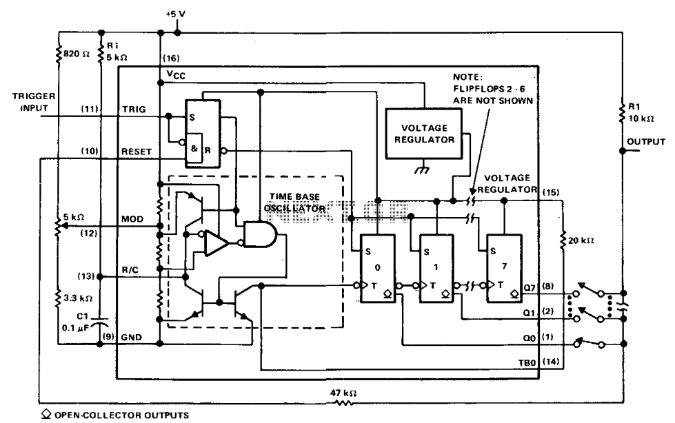
The µA2240 can be easily configured as a programmable voltage-controlled timer with a minimal number of external components. The modulation input (pin 12) allows for external adjustment of the input threshold level. A variable voltage is applied from the...
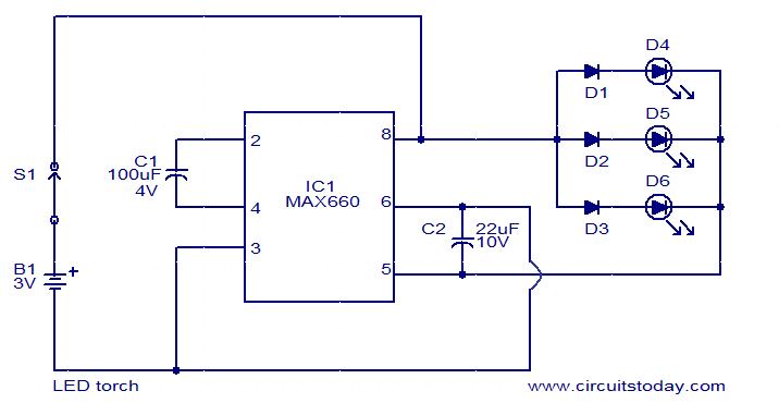
This is a simple LED torch circuit based on the MAX660 integrated circuit from MAXIM semiconductors. The MAX660 is a CMOS monolithic voltage converter IC capable of driving three bright white LEDs connected in parallel to output pin 8....