
150 watt amplifier circuit
The amplifier circuit is designed to deliver high-quality audio performance while maintaining simplicity and ease of assembly. The use of Darlington pairs provides high current gain, which is beneficial in achieving the desired power output without requiring complex circuitry. The differential amplifier configuration in the preamplifier stage plays a crucial role in reducing unwanted noise and improving the signal-to-noise ratio, which is essential for high-fidelity audio applications.
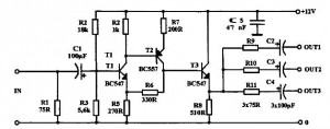
The circuit's layout can be implemented on a perf board, allowing for flexibility in component placement and ease of troubleshooting. The choice of components, such as the BC 558 transistors for the preamplifier and the robust TIP transistors for the output stage, ensures reliability and longevity in operation. The overall design philosophy focuses on achieving a balance between performance and simplicity, making it an ideal choice for hobbyists and audio enthusiasts looking to build a powerful amplifier on a budget.
When constructing the power supply, it is important to ensure that the transformer can handle the required load current, especially in stereo applications, where doubled ratings are necessary. Additionally, proper heat sinking for the TIP transistors should be considered to prevent thermal runaway and ensure stable operation under load. The design allows for customization and experimentation, making it a valuable project for those interested in audio electronics.This is the cheapest 150 Watt amplifier circuit you can get, I think. Based on two Darlington power transistors TIP 142 and TIP 147, this circuit can deliver a blasting 150 W Rms to a 4 Ohm speaker. Enough for you to get rocked, then try out this. TIP 147 and 142 are complementary Darlington pair transistors which can handle 5 A current and 100V, fam
ous for their ruggedness. Here two BC 558 transistorsQ5 and Q6 are wired as pre amplifier and TIP 142, TIP 147 together with TIP42 (Q1, Q2, Q3) for driving the speaker. This circuit is designed so rugged that this can be assembled even on a perf board or even by pin to pin soldering.
The circuit can be powered from a +/-45V 5A dual power supply. You must try this circuit. Its working great. The preamplifier section of this circuit is based around Q4 and Q5 which forms a differential amplifier. The use of a differential amplifier in the input stage reduces noise and also provides a means for applying negative feedback.
Thus overall performance of the amplifier is improved. Input signal is applied to the base of Q5 through the DC decoupling capacitor C2. Feedback voltage is applied to the base of Q4 from the junction of 0. 33 ohm resistors through the 22K resistor. A complementary Class AB push-pull stage is built around the transistors Q1 and Q2 for driving the loud speaker. Diodes D1 and D2 biases the complementary pair and ensures Class AB operation. Transistor Q3 drives the push-pull pair and its base is directly coupled to the collector of Q5. Remember TIP 142 and 147 are Darlington pairs. They are shown as conventional transistors in figure for ease. So don`t get confused. Even though each of them have 2 transistors, 2 resistors and 1 diode inside, only three pins, base emitter and collector are coming out.
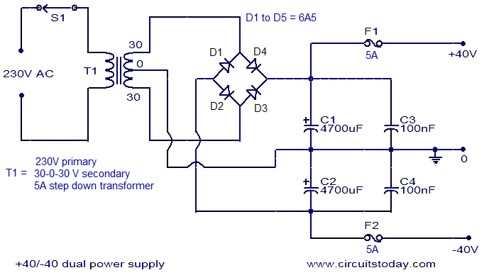
Rest are connected internally. So its quite OK to assume each of them as transistor for ease. A +40/-40 unregulated dual supply for powering this amplifier project is shown below. This power supply is only enough for powering one channel and for stereo applications double the current ratings of the transformer, diodes and fuses. 🔗 External reference
Related Circuits
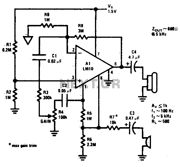
This circuit operates from a 5 V DC source. The described circuit is powered by a 5 V direct current (DC) supply, which is a common voltage level for many electronic devices and applications. The circuit may utilize various components...
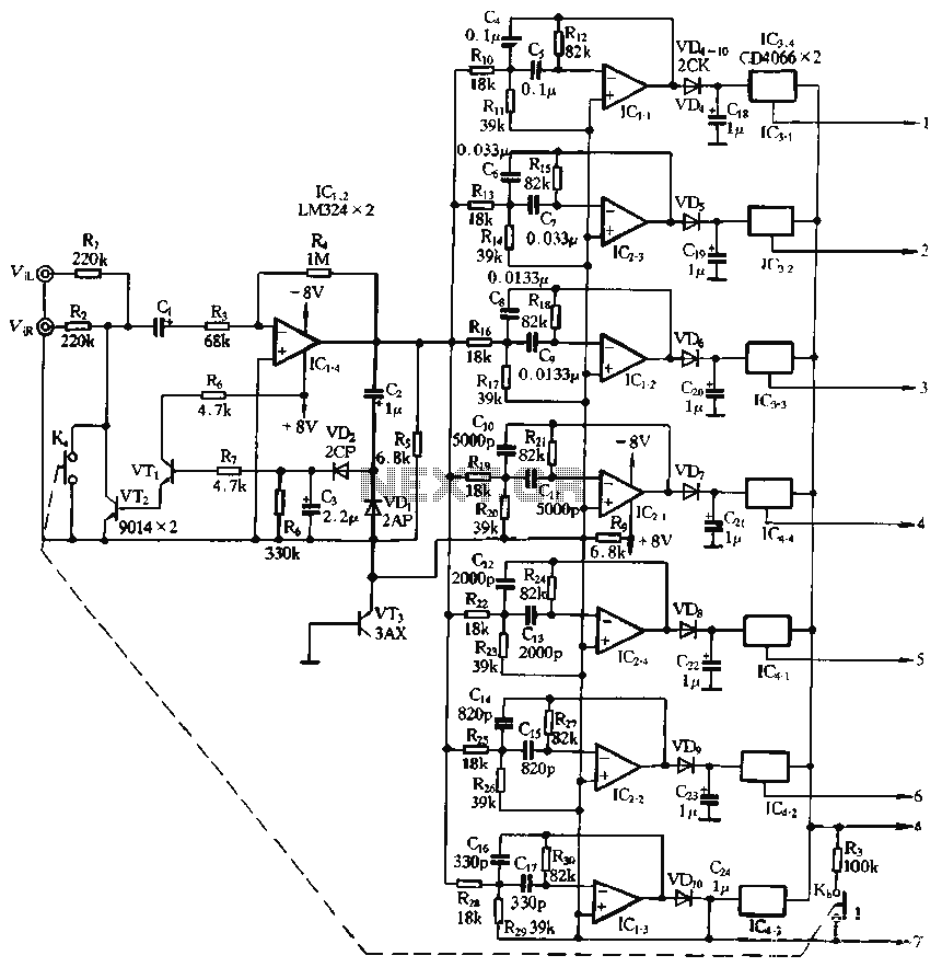
The structure and working principle of this circuit are fundamentally similar to the previous circuit, with some variations in the components used. The circuit is divided into seven bands, with center frequencies selected at 60 Hz, 150 Hz, 400...
A buffered video amplifier is utilized to connect a video player to a receiver or monitor TV over long cable lengths, which may lead to a reduction in signal amplitude and, consequently, a decline in image quality. This amplifier...
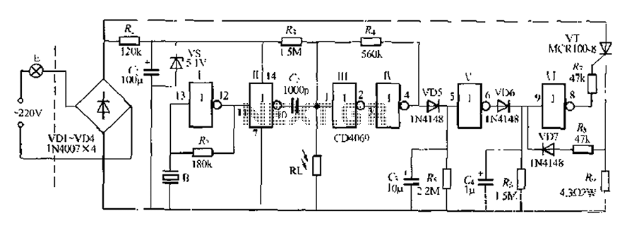
The circuit is designed for sound and light control of stairway and walkway lighting. It features high immunity and includes soft-start and over-current protection mechanisms. During the day, the photosensitive resistor has low resistance, resulting in a low voltage...
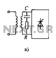
Diodes and thyristors have limited tolerance to over-current and over-voltage conditions. Short-term exposure to excessive voltage or current can damage these components and prevent them from achieving their full potential. The parameters of these devices should be determined based...
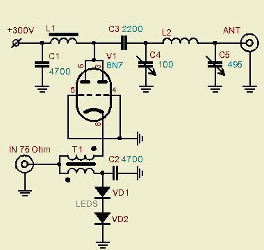
A powerful vacuum tube QRP amplifier designed for an 800mW QRPP homebrew telegraph vacuum tube transceiver named "3T." The decision to build this amplifier followed a period of using less than a watt of QRPP power for nearly a...