
Linear Video Amplifier SECAM PAL and NTSC

The buffered video amplifier circuit is designed to enhance signal integrity in video transmission systems. It employs a linear amplification method to maintain low noise levels, ensuring that the output signal closely resembles the input signal without introducing significant distortion. The bandwidth of at least 20 MHz allows it to accommodate the frequency range of standard video signals, making it suitable for various video formats.
Powering the amplifier with a stabilized voltage between 12 and 15 volts ensures reliable operation, while the low current consumption of 20 mA at 12 V minimizes the impact on the overall system power budget. The design's compatibility with AV connections, which separate audio and video signals, is critical to its functionality. This separation prevents interference between the audio and video signals, which could lead to degradation of signal quality.
In applications where multiple outputs are required, such as connecting several monitors to a single video source, the buffered video amplifier can be employed to split the signal without loss of quality. The ability to use two amplifiers—one for video and another for audio—further enhances flexibility in system design, allowing for tailored amplification based on specific requirements.
Overall, the buffered video amplifier is a vital component in video distribution systems, ensuring high-quality signal transmission over extended distances while accommodating various configurations and setups.Buffered video amplifier is used wherever the use of video player to the receiver / monitor TV with a long cable may cause a drop in signal amplitude and as a consequence, the deterioration in image quality. The amplifier can also be used to connect multiple receivers to one player or VCR. In any case, it prevents deterioration of picture quality as eating out edstvie greater load the player, or loss of signal power in the cable. This is a simple linear amplifier with low noise level with a broad band transfer (min 20 MHz) and increased ~ 6 dB. You can connect to any source of stabilized voltage 12-15 (in special cases even from the power supply VCR).
Current consumption of a small, 20 mA at 12 V. The scheme works only when using the compounds of AV where video and audio signals are sent separately. Not suitable for joints HF antenna cable. Make sure to include the video amplifier in the line of the video, while leaving the audio connection.
It is possible to use two amplifiers, one of which will be designed for the line video other audio. 🔗 External reference
Related Circuits
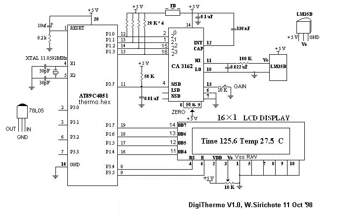
The A/D converter utilizes a dual-slope integrator to achieve a sampling rate of 10 Hz. The digital output sent to the microcontroller (MCU) is multiplexed in a four-bit Binary-Coded Decimal (BCD) format, starting from the Most Significant Digit (MSD),...
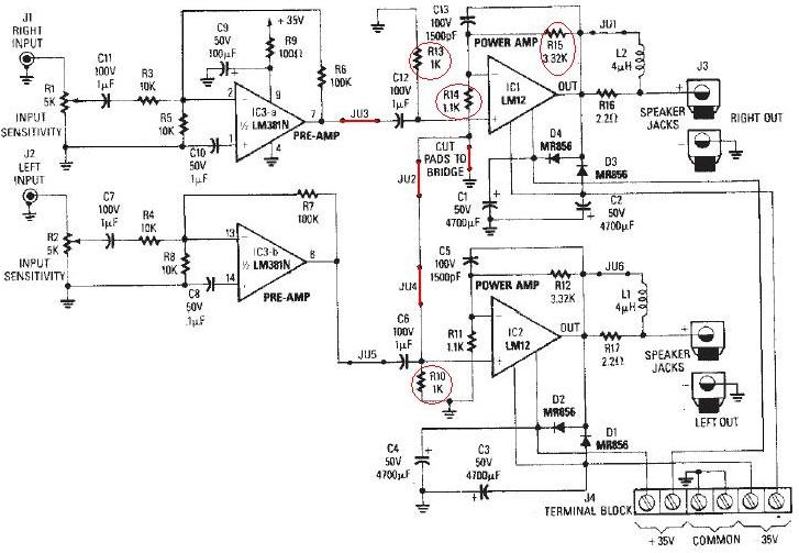
The LM12 audio amplifier circuit is designed to deliver high output power for loads with impedances of 4 ohms or 8 ohms. The maximum output power achievable by this amplifier is approximately 60 watts for a 4-ohm load and...
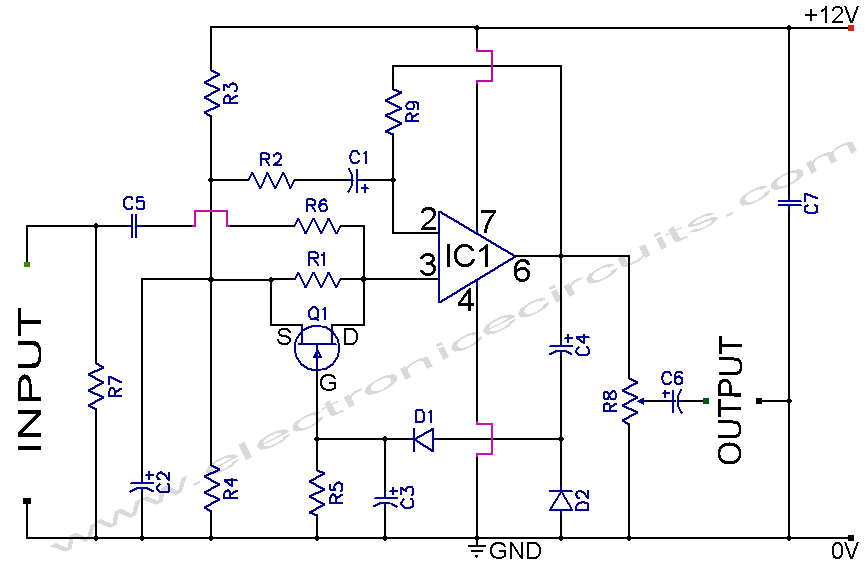
A section of the operational amplifier's output signal is rectified using 1N4148 diodes, followed by filtering, and is then directed to the gate of the FET input shunting circuit. As the output voltage increases, additional input shunting occurs, which...
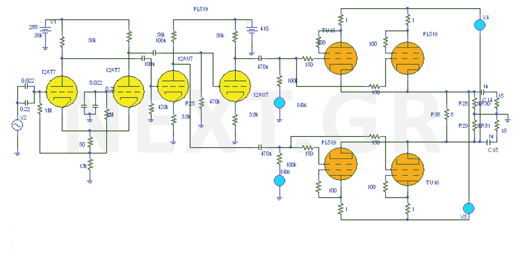
The design of the 40W Valve Amplifier is illustrated in the accompanying figure. Valve amplifiers are characterized by a prominent presence of second and third harmonics, sometimes accompanied by fourth and fifth harmonics, but always with a wider bandwidth....
This simple power MOSFET audio amplifier circuit utilizes a TL071C operational amplifier and two MOSFETs (IRF9530 and IRF530), capable of delivering up to 45 Watts to an 8-ohm speaker. The schematic is based on a Siliconix application and incorporates...
Main Power Amplifier OCL 100 watt using MJ802 and MJ4502 transistors. It is designed to provide strong bass and bold treble, making it suitable for various applications such as parties or home theater systems. This Class AB amplifier delivers...