
1500A-7V-phase thyristor power regulator circuit a plating

The 1500A-7V phase thyristor power regulator circuit is designed to manage power levels in plating processes, where precise control of voltage and current is essential for achieving high-quality finishes. The main circuit is responsible for the high-power handling capabilities, allowing it to manage substantial currents up to 1500A at a voltage of 7V.
The control circuit plays a critical role in regulating the output voltage and current. It incorporates a trigger circuit that activates the thyristors based on the input voltage conditions. The synchronous power supply ensures that the control circuit operates reliably under varying load conditions. The use of a potentiometer, RP4, allows for fine-tuning of the input voltage, which is essential for maintaining the desired operational parameters.
Protection mechanisms are integrated into the design to prevent damage to the circuit components during overload conditions. The potentiometer RP3 sets the threshold for normal operation, and the regulator VS3 monitors the system's performance. If the current exceeds the preset limits, VS3 may fail, triggering a series of events where VT2 becomes conductive while VT1, VT3, and VT4 turn off. This sequence effectively deactivates the thyristors, thus disconnecting the main circuit and safeguarding the entire system from potential damage due to overcurrent.
Overall, this thyristor power regulator circuit is an essential component in industrial plating applications, ensuring both performance and safety through its well-designed control and protection features.1500A-7V-phase thyristor power regulator circuit a plating It consists of the main circuit, control circuit and the protection circuit has three major components. The control c ircuit includes a trigger circuit, synchronous power supply and other components. Given voltage Ug superimposed (given by the RP4) and synchronous voltage control transistor trigger circuit board VT5 work like state. When the circuit is overloaded (set value set by the potentiometer RP3, under normal circumstances, the regulator VS3 no breakdown), VS3 hit wear, VT2 conduction, VTi off, VT3, VT4 off thyristors closed, cutting off the main circuit, reaches overcurrent protection purposes.
Related Circuits
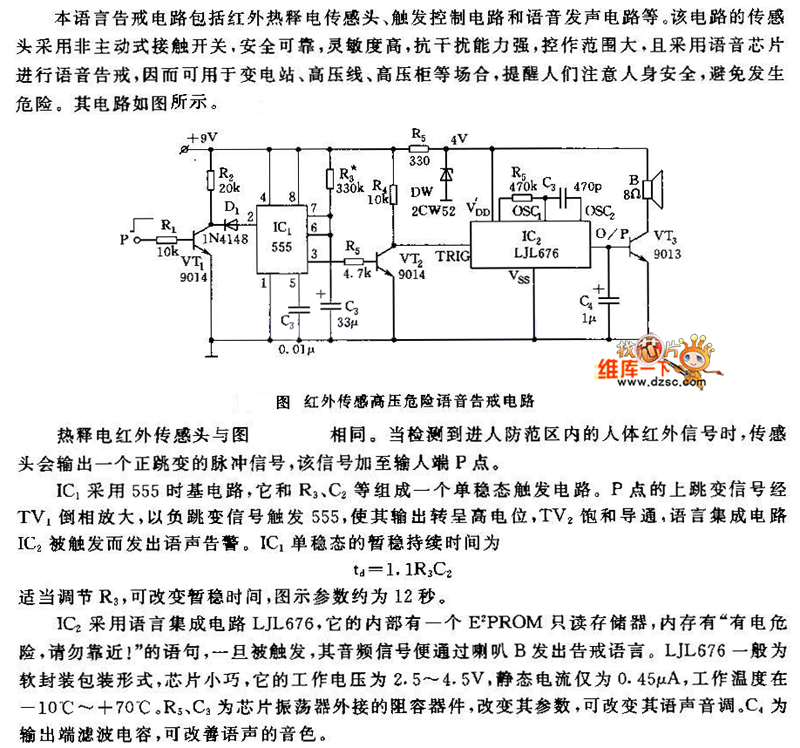
The pyroelectric infrared sensor head operates as illustrated in the accompanying figure. Upon detecting an infrared signal from a human body within its monitoring zone, the sensor head generates a positive pulse signal. This signal is transmitted to the...
The circuit is presented, consisting of a language and sound circuit FM transmitter. It is simple and easy to manufacture, compatible with ordinary FM radios, allowing for potential listening scenarios and preventive measures. The FM transmitter circuit is designed to...
Color TV main power protection circuit The color TV main power protection circuit is designed to safeguard the television's power supply from various electrical anomalies, such as overvoltage, undervoltage, and short circuits. This circuit typically employs several components, including fuses,...
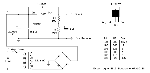
The LM317T is an adjustable three-terminal positive voltage regulator capable of supplying more than 1.5 amps with an output range of 1.25 to 37 volts. The device features built-in current limiting and thermal shutdown, making it robust against failure....
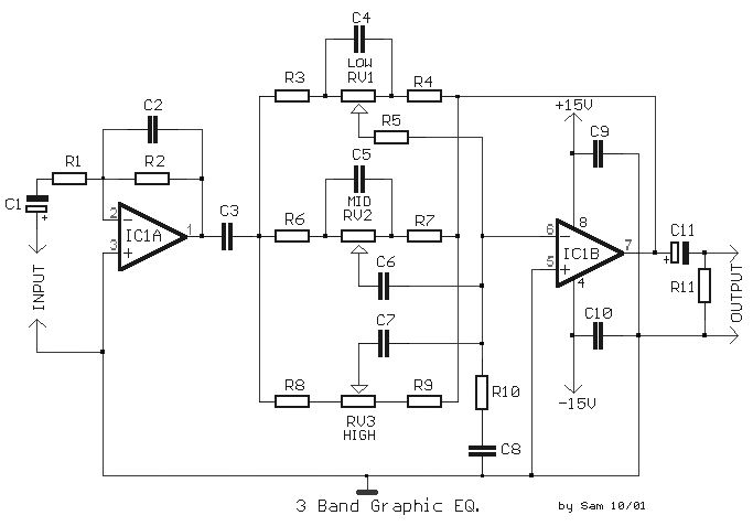
The circuit illustrates the use of three frequencies to produce a graphic equalizer that will be used for acoustic signals. The equalizer can be either passive or active. The graphic equalizer circuit operates by dividing the audio frequency spectrum into...

This circuit generates sine and square wave signals with frequencies ranging from below 20 Hz to above 20 kHz. The advantage of this circuit diagram is that the output frequency can be adjusted by varying the variable resistor R6. The...