
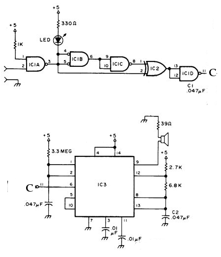
3 Band Graphic Equalizer Circuit

The graphic equalizer circuit operates by dividing the audio frequency spectrum into multiple bands, typically centered around specific frequencies. In this case, the circuit utilizes three distinct frequency bands, which allows for the adjustment of the amplitude of audio signals within those bands.
The design may incorporate either passive components, such as resistors, capacitors, and inductors, or active components, including operational amplifiers, depending on the desired performance and application. In a passive equalizer, the frequency response is shaped through the use of passive filters, which do not amplify the signal but rather attenuate certain frequencies. Conversely, an active equalizer employs amplifiers to provide gain, allowing for greater control over the output signal and the ability to boost specific frequency ranges.
The circuit typically includes a set of sliders or knobs that allow the user to adjust the gain for each frequency band. These adjustments modify the audio signal's frequency response, enhancing or diminishing specific frequencies to achieve the desired sound profile. The output of the equalizer can then be fed into an audio amplifier or directly to speakers.
In addition to the basic components, careful consideration is required for the selection of the center frequencies and the bandwidth of each band, as these factors significantly influence the overall performance of the equalizer. The design may also include additional features such as bypass switches, which allow the user to compare the equalized signal with the original audio signal, and LED indicators to provide visual feedback on the settings being used.
Overall, the graphic equalizer circuit serves as a powerful tool for audio processing, enabling users to tailor acoustic signals to their preferences or to compensate for deficiencies in the sound system or listening environment.The circuit illustrates the use of 3 frequencies to produce a graphic equalizer that will be used for acoustic signals. Equalizer a passive or an active.. 🔗 External reference
Related Circuits
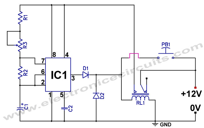
The standard 555 timer circuit consumes power from the battery even when the start push-button (PB1) is not pressed, due to a potential divider created by three 5kΩ resistors within the integrated circuit (IC). This power consumption, referred to...
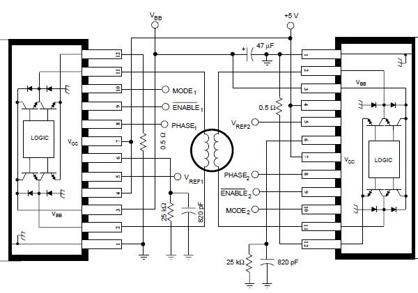
The A3952S stepper motor controller, designed by Allegro MicroSystems, can be utilized to create a straightforward and effective motor driver circuit suitable for various electronic applications. This controller supports continuous output currents of up to 2 A and operates...
The hardware schematic for the robotic arm, referred to as the wooden menace, is quite straightforward. The PIC microcontroller has one control line connected to each servo and also connects to an RJ45 connector, which is used to receive...
A larger version of the circuit diagram can be accessed by clicking here. The circuit was created using Eagle from CadSoft, which is a free schematic and PCB layout software for small non-commercial projects. The core component of the...
The NE556 timer can function as an indicator for the static state of a digital logic audible terminal. An audible logic probe is beneficial for visually inspecting a component while simultaneously checking the logic state at another point far...
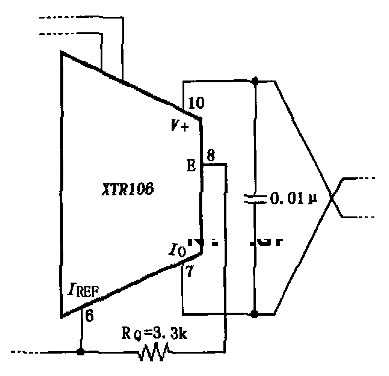
The circuit has been simplified due to the cancellation of an external transistor. The connection between the emitter terminals of the original external transistor and a 3.3k resistor will be removed, as this change has led to a decrease...