
Infrared sensor high voltage dangerous voice warning circuit diagram

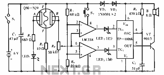
The pyroelectric infrared sensor head is designed to detect infrared radiation emitted by human bodies, making it suitable for applications such as motion detection, security systems, and automatic lighting. The sensor head typically consists of a pyroelectric element that generates a voltage when exposed to varying infrared radiation levels. This voltage change, when a human body enters the detection zone, is converted into a positive pulse signal.
The 555 timer IC, configured in a monostable mode, is an essential component of this circuit. In this configuration, the output remains low until a triggering event occurs, which in this case is the positive pulse signal from the sensor head. The resistor R3 and capacitor C2 determine the duration of the output pulse. When the signal at point P is received, the 555 timer generates a single output pulse whose width is defined by the time constant of R3 and C2. This output can be used to trigger additional circuits or systems, such as alarms or lights, enhancing the functionality of the sensor system.
The amplification of the pulse signal ensures that it is strong enough to drive subsequent components in the circuit. The design of this sensor system is critical for ensuring reliable operation in various environments, and careful selection of components such as R3 and C2 is necessary to tailor the response time and sensitivity of the system to meet specific application requirements.Pyroelectric infrared sensor head is same with the figure. When it detects the human body infrared signal in guarding zone, the sensor head will output a positive jump pulse signal, this signal is added to input terminal P point. IC1 adopts 555 time base circuit, the monostable trigger circuit is composed of 555 and R3, C2. P`s jump signal is phased and amp.. 🔗 External reference
Related Circuits

The CCD camera sensor is a very useful device that is compact in size while providing excellent quality. It can be easily installed with a television through the video input terminals, allowing for the transmission of modulated video signals...
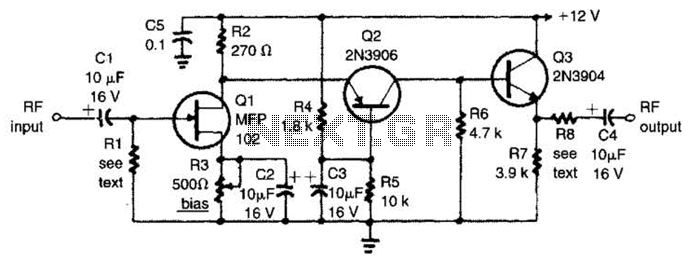
The circuit features a frequency response that spans from 100 Hz to 3 MHz, with a gain of approximately 30 dB. Field-effect transistor Q1 is arranged in a common-source self-biased configuration, and an optional resistor R1 is available to...
The QM-NJ9 is an alcohol sensor that detects the presence of alcohol by measuring the resistance values between points A and B. When alcohol is detected, the resistance decreases, leading to an increase in potential at point B. As...
This is a simple LED night light circuit that can serve as a room night lamp. The circuit is straightforward and can be constructed with a few components. It employs four LEDs to function as a night lamp. Users...

The following circuit diagram of a dual voltage power supply can be used for miscellaneous applications. It requires a few components to build. The most important components of this circuit are regulators: 1: (AN) 7812 and 2: (AN) 7912....

This is the complete circuit of the modern homodyne receiver. This receiver can receive AM, CW, and SSB transmissions. The modern homodyne receiver is a sophisticated device designed to process various types of radio frequency signals, specifically Amplitude Modulated (AM),...