
Two-Tone Siren Circuit Schematic Using One IC

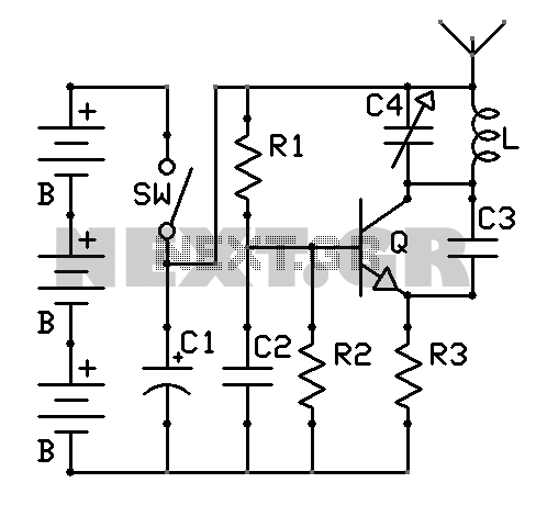
The Two-Tone Siren Circuit utilizes a single integrated circuit (IC) to generate two distinct audio tones, providing an engaging sound effect suitable for various applications. The circuit typically consists of a 555 timer IC configured in astable mode, which allows it to produce a square wave output. The frequency of this output can be adjusted using resistors and capacitors connected to the timer.
Key components of the circuit include:
1. **555 Timer IC**: This is the core component responsible for generating the two-tone sound. The frequency of oscillation can be modified by changing the values of the resistors (R1, R2) and the capacitor (C1) connected to the timer.
2. **Resistors and Capacitors**: These components determine the frequency of the tones produced. By using a combination of resistors and capacitors, the circuit can create a pleasing sound pattern that alternates between two different frequencies.
3. **Speaker**: A small speaker or piezo buzzer is connected to the output of the 555 timer. This component converts the electrical signals from the IC into audible sound.
4. **Power Supply**: The circuit is powered by a battery, making it suitable for mobile applications. A typical voltage range would be between 3V to 9V, depending on the specifications of the components used.
5. **Switch (SW1)**: This component allows users to turn the circuit on and off, providing control over the sound output.
The circuit is compact and can be easily integrated into various devices such as toys, models, and small vehicles. The design is user-friendly, allowing for simple assembly and modification. The playful sound generated by the siren can enhance the enjoyment of children while being used in recreational activities.Two-Tone Siren Circuit Schematic Using One IC Circuit This circuit is intended for children fun, and can be installed on bicycles, battery powered cars and motorcycles, but also on models and various games and toys. With SW1 pos.. 🔗 External reference
Related Circuits
A touch dimmer circuit is illustrated in the accompanying diagram. It utilizes a finger touch control piece to enable the turning on, off, or stepless adjustment of incandescent lighting. This circuit is applicable in dimming filament lamps and for...
The sound produced mimics the rise and fall of an American police siren. When first powered on, the 10µF capacitor is discharged, and both transistors remain off. Upon pressing the push button switch, the 10µF capacitor begins to charge...
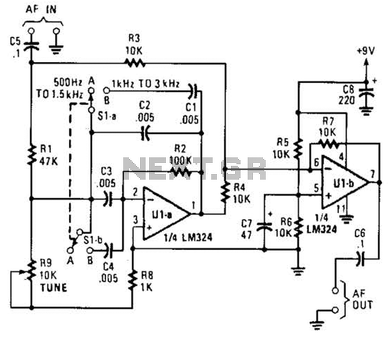
The notch filter can be integrated into nearly any receiver to attenuate a specific frequency by over 30 dB. This filter is particularly useful for diminishing heterodynes and whistles. A notch filter, also known as a band-stop filter, is designed...
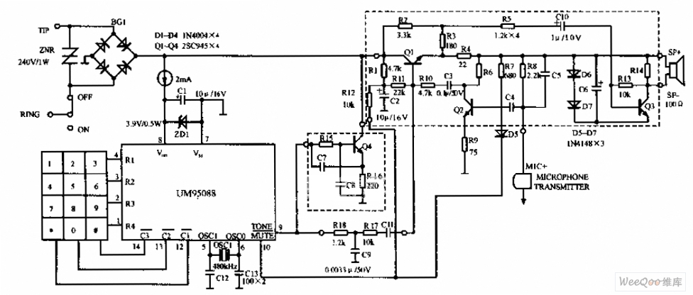
The UM95088 telephone circuit diagram is depicted in the image above. The UM95088 is a specialized integrated module designed for dual-tone multi-frequency (DTMF) telephone dialing. It utilizes CMOS technology and comes in a 14-pin dual-in-line package. The schematic for...
There are neighbors who may disturb you with loud televisions or radios. A solution is available. This jammer emits jamming waves that affect the TVs and radios in the neighborhood, so caution is advised. This device is an enhanced...
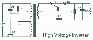
A 3V to 1000V inverter circuit has been constructed, but it is not functioning as intended. The creator seeks expert assistance to identify potential errors in the circuit design. Additionally, there is uncertainty regarding the transformer construction, as the...