
15v variable power supply circuit

This power supply circuit utilizes the robust 2N3055 power transistors, which are known for their high current capacity and thermal stability. The circuit is designed to provide a variable output voltage, adjustable from 1.5V to 15V, making it suitable for a variety of applications that require different voltage levels. The maximum output current of 500 mA ensures that it can power moderate loads effectively, while the stabilization feature maintains output voltage accuracy within a tolerance of 2% under specified load conditions.
The voltage adjustment is achieved through a potentiometer, allowing users to set the desired output voltage easily. The inclusion of an overload protection mechanism is critical for safeguarding both the power supply and connected devices. The T4 transistor plays a pivotal role in monitoring the output voltage. It continuously compares the voltage at the adjustable potentiometer (P1) with the output voltage. When the output voltage exceeds the regulated level by 0.65V, T2 is triggered, which in turn controls the Darlington pair formed by T3 and T5, effectively reducing the output current to prevent damage due to overload.
The reference voltage for the T4 transistor is supplied by a 15V zener diode, ensuring a stable reference point for the voltage comparison. This design feature enhances the reliability of the overload protection circuit, ensuring that the power supply operates safely across its entire range of output voltages. Overall, this 15V variable power supply circuit is an effective solution for applications requiring adjustable voltage and robust current handling capabilities.This 15v variable power supply electronic project is designed using 2N3055 transistors. Output voltage of this variable power supply can be adjusted in the range between 1. 5 and 15 volts. This 2N3055 15v variable power supply can provide a maximum current of 500 mA. Stabilization is better than 2%, if the currents do not exceed 350 mA. Voltage is set using a potentiometer, and the presence of overload is announced by an audible indication of overload. T4 transistor compare the voltage at the cursor P1 with the output. When this voltage is higher with 0. 65 V than regulated voltage, T2 opens, leading to suppression of the current Darlington power stage, T3-T5.
In this mode, the output voltage of the source is higher than 0. 65 V reference voltage on the base of T4, which comes from a 15 V zener diode. 🔗 External reference
Related Circuits

Large LCD devices with one or more displays exhibit significant driving capacitance to the driver circuits. To address this issue, the drive circuit incorporates a buffer amplifier for each of the three common lines. Each amplifier can be programmed...

Biasing methods for an N-channel MOSFET to form a unity-gain noninverting amplifier or source-follower. The N-channel MOSFET can be utilized in various configurations, with one common application being the unity-gain noninverting amplifier, also known as a source-follower. In this configuration,...
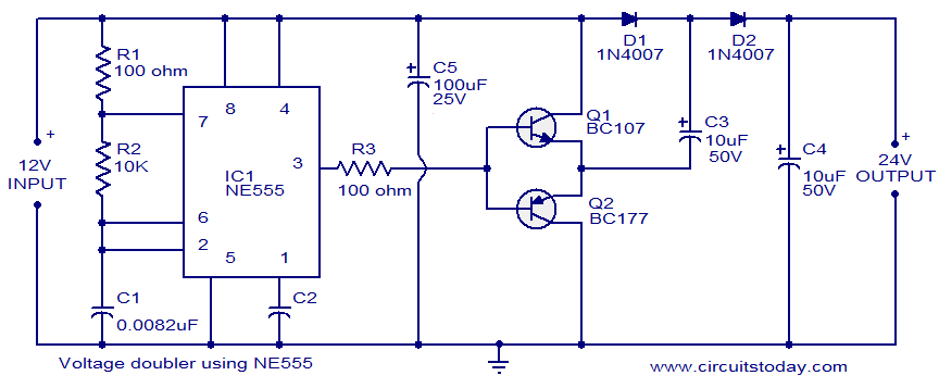
This circuit demonstrates a voltage doubler utilizing the NE555 timer. It is a straightforward project. The NE555 integrated circuit is configured as an astable multivibrator. The NE555 timer is a versatile component commonly used in various electronic applications, including timing,...

This article presents a diagram of an attenuated tone control circuit. The circuit primarily consists of transistors and RC networks as its components. The circuit operates in such a way that the shunt effect of capacitor C4 and resistor...

The circuit is illustrated. It includes a DC power circuit with a power switch (S3) that converts 220V AC voltage through a buck converter (T), a rectifier (UR), and filter capacitors (C3 and C4) to generate a +9V output....
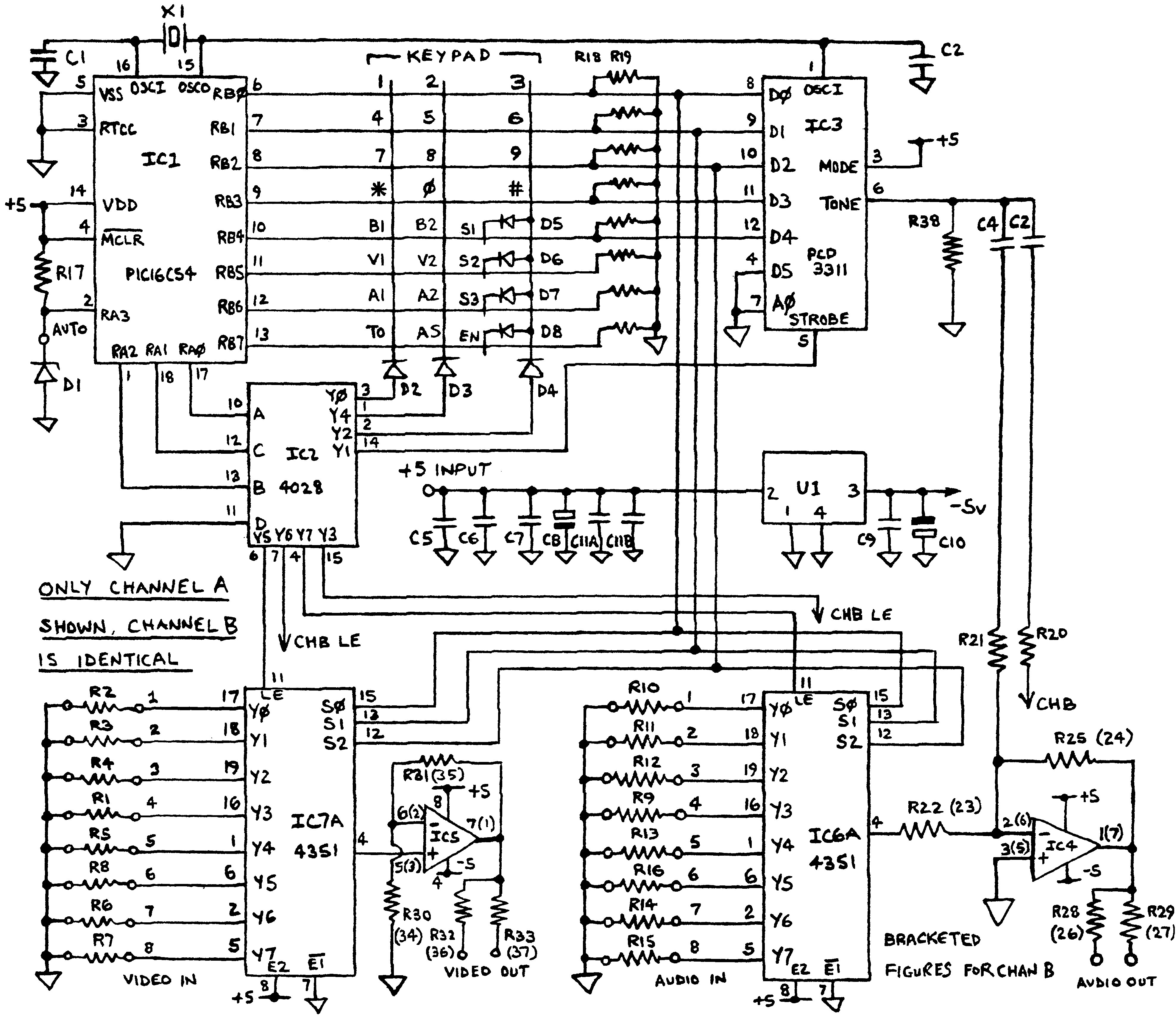
Before applying power, check for shorts on the board. This design operates from a 5V supply; connecting it directly to a 12V supply will certainly damage it. The current draw is minimal, approximately 70mA, so if using a 12V...