
Unity-Gain Noninverting Amplifier Circuit

The N-channel MOSFET can be utilized in various configurations, with one common application being the unity-gain noninverting amplifier, also known as a source-follower. In this configuration, the MOSFET operates in the saturation region, where it can effectively buffer an input signal while maintaining the same voltage level at the output.
To achieve the desired biasing for the MOSFET, several methods can be employed. One common approach is to use a resistor divider network connected to the gate terminal of the MOSFET. This network establishes a stable DC voltage that sets the operating point of the device. The gate voltage must be sufficiently above the source voltage to ensure that the MOSFET remains in the saturation region throughout the input signal's range.
Another method involves using a current source to provide a constant biasing current to the MOSFET's source terminal. This arrangement helps stabilize the operating point against variations in temperature and device parameters, enhancing performance consistency.
The output of the source-follower configuration is taken from the source terminal of the MOSFET, which closely follows the input voltage while providing high input impedance and low output impedance. This characteristic makes the source-follower ideal for impedance matching applications, where it can drive loads without significant voltage drop.
In summary, employing biasing methods for an N-channel MOSFET in a unity-gain noninverting amplifier configuration allows for effective signal buffering with high input impedance and low output impedance characteristics, making it a valuable component in various electronic applications. Biasing methods for an N-channel MOSFET to form a unity-gain noninverting amplifier or source-follower.
Related Circuits
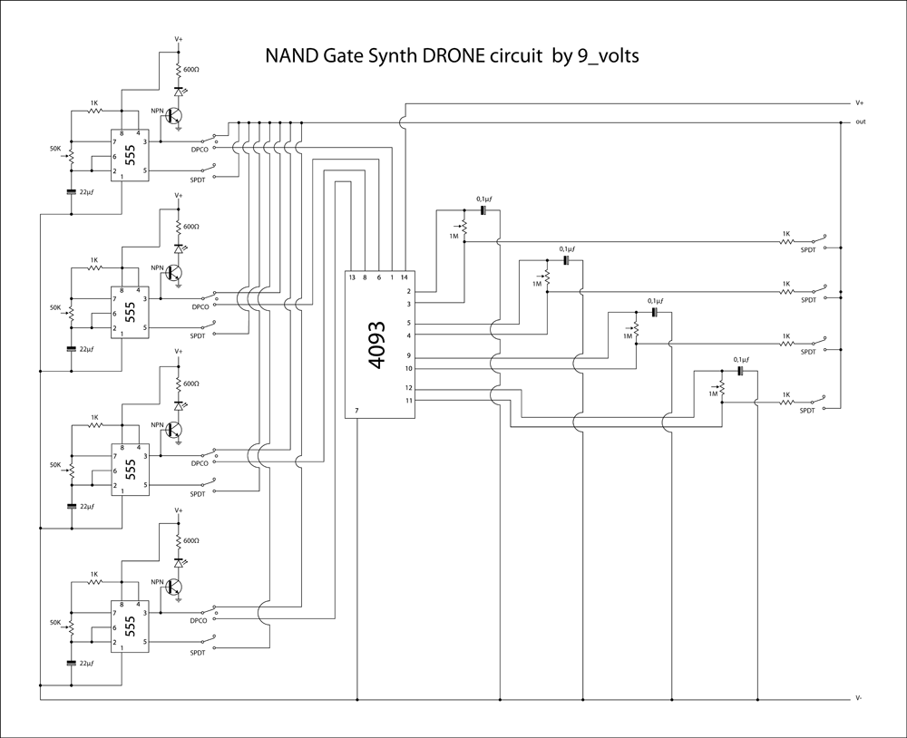
This is a brief jam session to explore the capabilities of a recently completed step sequencer. This device is quite enjoyable and expands creative possibilities. A detailed post with the circuit and instructions for building it will be provided...

The schematic for this project is visually acceptable, although it is not the most refined layout for a schematic. The basic flow progresses from left to right, starting with the state machine, followed by the 555 timers, then the...
An infrared wired repeater circuit is designed to control appliances from a remote location. Parts List: R1: 1k Resistor (1), R2: 3.3k Resistor (1), R3: 10k Resistor (1). The infrared wired repeater circuit serves as an interface for controlling various...

This is a simple circuit design for a two-station intercom system utilizing common 8-ohm mini speakers. The press-to-talk switches should feature a spring-return mechanism to ensure that the intercom cannot be left in the ON position. The circuit requires...
A gas leak detector circuit that detects the leakage of LPG gas and alerts the user through audio-visual indications. The circuit operates off a 9V PP3 battery. A Zener diode is used to convert 9V into 5V DC to...
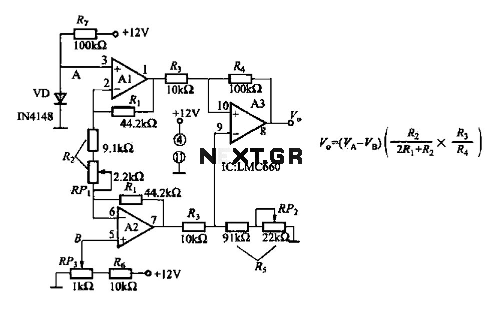
A diode IN4148 temperature circuit is presented. The circuit operates within a temperature range of -25 to 125 degrees Celsius, with an accuracy of 0.5. The core components of the operational amplifier circuit consist of four LMC660 amplifiers. It...