
NE555 IC For Voltage Doubler Circuit

The NE555 timer is a versatile component commonly used in various electronic applications, including timing, pulse generation, and waveform generation. In this configuration as an astable multivibrator, the NE555 operates continuously in a cycle of charging and discharging, generating a square wave output.
To create a voltage doubler, the output from the astable multivibrator can be used to drive a rectifier circuit, typically composed of diodes and capacitors. The output square wave signal from the NE555 is applied to a diode, which allows current to flow in one direction, charging a capacitor. When the output goes low, the charged capacitor retains the voltage, and the next cycle of the square wave adds to this voltage, effectively doubling the output voltage.
The circuit typically consists of the NE555 timer connected with two resistors and a capacitor to set the frequency of oscillation. The output pin (pin 3) of the NE555 connects to the anode of the first diode, while the cathode connects to the first capacitor. The second diode is connected to the output of the first capacitor, allowing the second capacitor to charge to a higher voltage level.
For optimal performance, the values of the resistors and capacitors should be selected based on the desired output frequency and voltage levels. Additionally, the choice of diodes is crucial; they should have a low forward voltage drop to maximize efficiency.
The voltage doubler circuit using the NE555 timer is suitable for applications requiring a higher voltage from a lower voltage source, such as powering small electronic devices or charging capacitors in various circuits. Proper attention to component specifications and circuit layout will ensure reliable operation and performance.This following circuit shows a voltage doubler using NE555 timer. This is a simple project. The NE555 IC is wired as an astable mutivibrator .. 🔗 External reference
Related Circuits
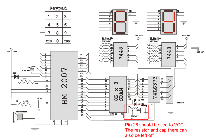
Verify the pin configurations on the datasheets for the integrated circuits used in your project, making necessary adjustments. In this instance, the RAM chip utilized had a non-inverted enable signal on pin 26, while the schematic assumed it was...
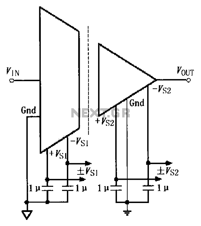
The basic connection circuit for the ISO122/124 includes power and signal connections. Each supply terminal of the ISO122/124 must be equipped with a 1 µF tantalum capacitor serving as a bypass filter. It is important to position the printed...
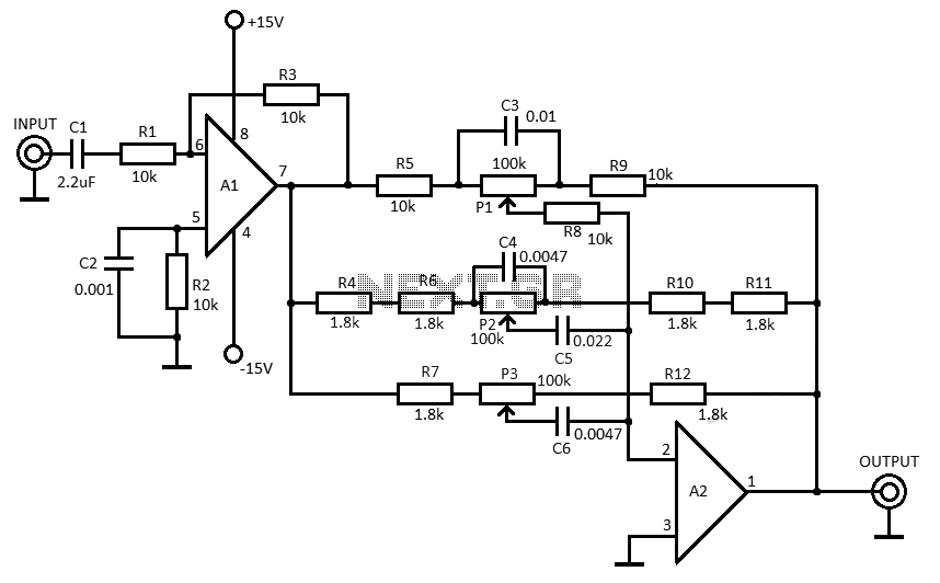
This 3-band equalizer circuit is an active filter network designed to adjust bass, midrange, and treble audio frequencies. It utilizes the LM833 operational amplifier from National Semiconductors, which is known for its very low noise figure and wide frequency...
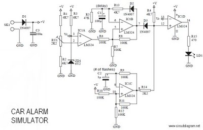
This is a car alarm simulator that uses an LED as a simulation output. This simple circuit can indicate whether a car is running by detecting the voltage difference when the car is on and off. When the car...
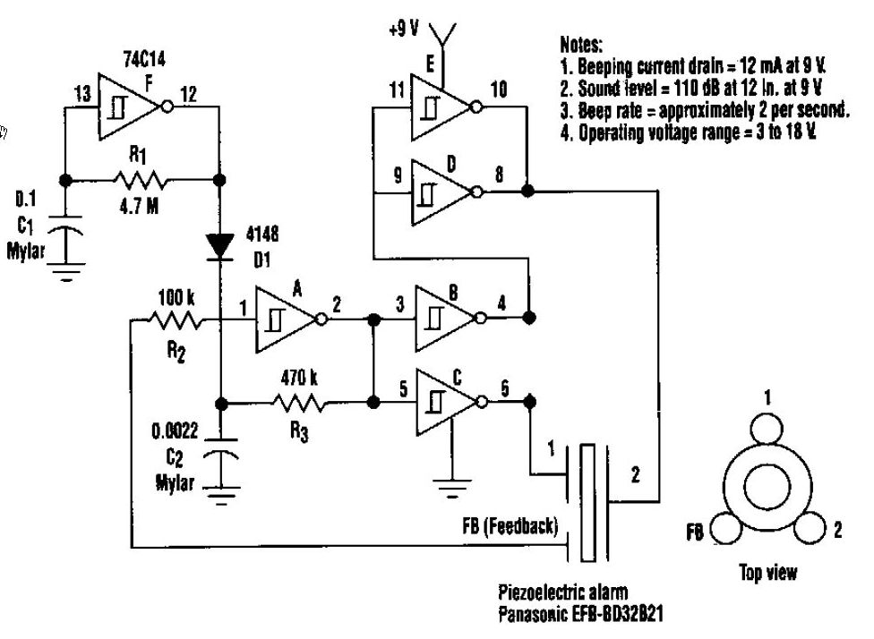
This beeper circuit generates an impressive 110dB sound level from a 9V supply. The design employs a single 74C14 (CD40106B) CMOS hex inverting Schmitt-trigger integrated circuit (IC), which must be paired with a piezoelectric device featuring a feedback terminal....
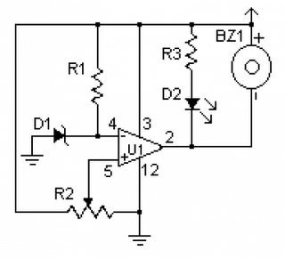
A low voltage monitor circuit is essential for security and protection against potential damage to equipment, particularly for vehicles. This circuit is relatively simple to construct, utilizing the LM339 integrated circuit. The operation of this circuit involves activating a...