
16-channel remote control circuit schematic (T998C)
")
The circuit design incorporates a dual-functionality mechanism, enabling it to switch between latch and non-latch output modes based on the state of the control switch (SB) and the supply voltage (VDD). In the latch output state, the circuit retains the last output state even after the control signals are removed, making it suitable for applications requiring memory or state retention.
When the SB switch is closed, and VDD is supplied, the circuit enters a stable latch state. The sixteen output terminals are then capable of reflecting the Io output state, which can be derived from various input signals or conditions within the circuit. This configuration is particularly useful in digital applications where specific states need to be held until explicitly changed.
In the non-latched output state, achieved by connecting SB directly to the Io output terminals, the outputs are dynamically controlled. This mode allows for real-time response to input changes, making it ideal for applications such as signal routing or multiplexing, where immediate output changes are necessary without retaining previous states.
Overall, the design of this circuit offers versatility in electronic applications, allowing for both temporary and permanent output states, thereby enhancing functionality in various digital systems. The careful selection of components and the arrangement within the schematic ensure reliable operation across both modes.The circuit is not only used for the latch output, but also for non - latched output, SB is control switch. When SB and VDD are turned on, it is in the latch output state, then the sixteen output ends are out control of Io output state; when SB and Io output ends are connected, it is in non- latched output state, then the output states are under control of I..
🔗 External reference
Related Circuits
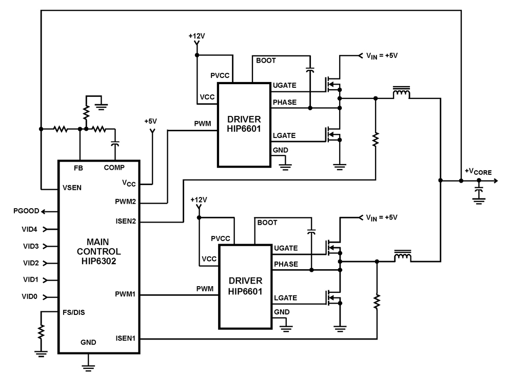
The HIP6302 Multiphase PWM control IC, along with its companion gate drivers (HIP6601, HIP6602, or HIP6603) and Intersil MOSFETs, delivers a precise voltage regulation system for advanced microprocessors. Multiphase power conversion represents a significant advancement over traditional single-phase converter...
This circuit is designed to demonstrate high frequency and high voltage, capable of producing up to approximately 30 kV, depending on the transformer utilized. It is an economical and straightforward project, primarily using a standard TV flyback transformer. The...
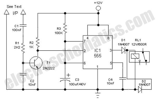
This is a simple toggle switch that can be operated through sound signals such as a whistle or clap. The output of the toggle remains either low or high until... This circuit utilizes a sound sensor to detect specific audio...
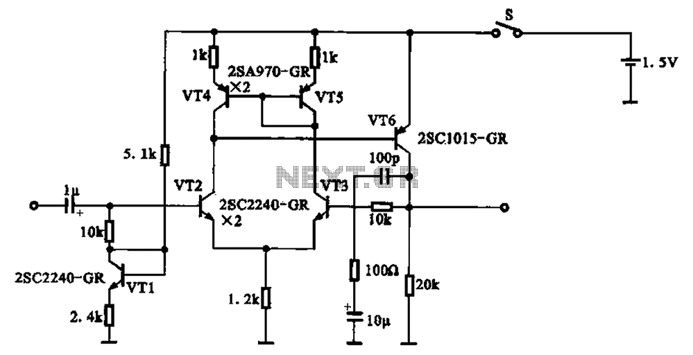
A 1.5V-powered microphone signal amplifying circuit is designed with a power supply for the microphone signal amplification. The circuit primarily consists of a differential amplifier formed by transistors VT2 and VT3. Additionally, VT6 functions as a common emitter voltage...
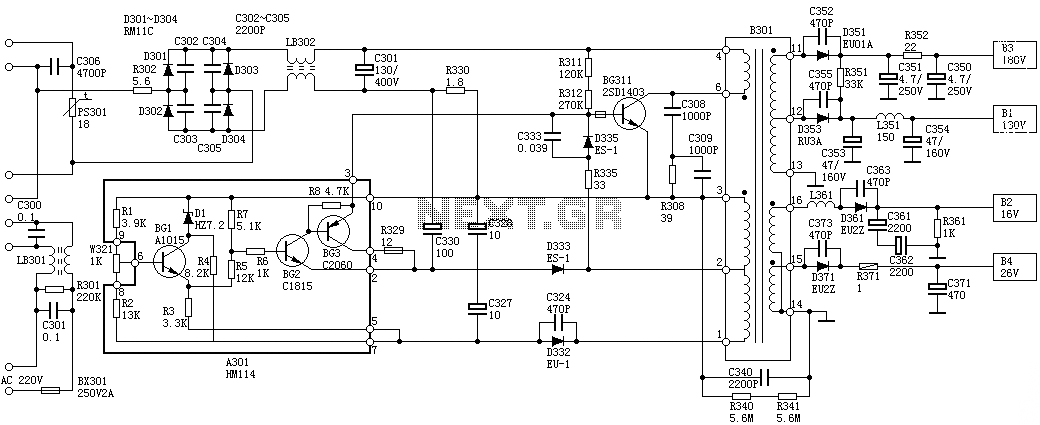
Oscillation: The positive terminal voltage of C310 is approximately 300V. The resistors R311 and R312 are connected to the switch BG311 at the B pole, while the B301 winding via the switching transformer (4) and (6) is connected to...
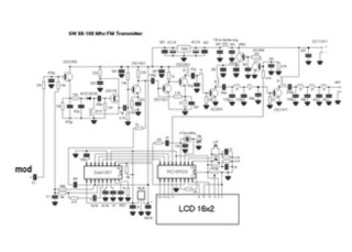
This is a straightforward high-quality PLL FM transmitter with a typical output power of 5 W and a no-tune design. It features RDS/SCA input and audio/MPX input with optional pre-emphasis and can operate with or without a stereo encoder....