
stereo fm circuit

The transmitter can function without an LCD display. Some experience in building similar devices is highly recommended. The supply voltage ranges from 11 to 13.8 V (either stabilized or from a battery), with a maximum supply current of 1.2 A. The standard frequency range is from 87.5 to 107.9 MHz. The audio/MPX input sensitivity is 2 V pp for a frequency deviation of 75 kHz, and the RDS/SCA input sensitivity is 0.2 V pp for a frequency deviation of 7.5 kHz. The board dimensions are 109 x 54 mm.
Key components include Q1 (BF240), Q2 (BFG135 or BFG235), Q3 (2SC1971 or 2N3553 with heatsink), Q4 (BC547B), D1 (SB260, 1N5822, or 1N581x), D2 and D3 (BBY40 or BBY31), D4 (5mm LED), U1 (78L09), U2 (TSA5511, TSA5512, or SDA3202 in DIL socket), U3 (PIC16F627A in DIL socket, programmed), and U4 (78L05). Resistors include R1, R2, R11, R17, R20 (10k), R3, R21 (270R), R4, R15 (33k), R5, R7, R12, R13, R16 (680R), R6, R14 (18k), R8 (47R or 33R if Q2 is BFG235), R9 (18R), R10 (4k7), R18 (3k3), R19 (100k SMD 1206), R22 (91R), and R23 (5k mini trimmer). Capacitors include C1, C4, C9, C12, C13, C14, C15, C30, C31, C32, C33, C35 (10n SMD 1206), C2, C17, C20 (15p), C3 (10p or 15p if the PCB is single-sided), C5 (1n), C6, C28, C29, C34 (100u/10V), C7, C26 (10u/35V), C8 (22p), C10 (47p or 33p if Q3 is 2N3553), C11, C27 (100n), C16, C36 (33p), C18 (50p capacitor trimmer), C19 (470u/16V), C21 (4u7/50V), C22 (330p), C23, C24 (47p), and C25 (3n3 P).
Inductors include L1 (3.5 turns on 7 mm diameter), L2 (1uH/815mA choke or about 10 turns of thin wire on mini ferrite core), L3 (2.5 turns on 6 mm diameter or 4.5 turns if Q3 is 2N3553), L4 and L5 (3.5 turns on 6 mm diameter). The crystal used is Y1 (6.4 MHz or 3.2 MHz). TR1 is an RF ferrite transformer with a 2:1 ratio (3:1 if Q3 is 2N3553).
Switches SW1 and SW2 are mini buttons. Connectors include J1, J2, J3 (BNC connector 90 degrees), J4 (power supply connector), J5 (HD44780 LCD standard connector, either 2x8 or 2x16 characters), and J6, J7 (jumpers).
This PLL FM transmitter is designed for versatility and ease of use, making it suitable for hobbyists and professionals alike. Its modular design allows for customization and integration into various audio and broadcasting applications. The use of a dual-speed PLL for tuning ensures stability and accuracy in frequency selection, while the option for RDS/SCA input enhances the functionality of the transmitter for advanced broadcasting needs. The careful selection of components and the inclusion of both analog and digital elements provide a robust platform for FM transmission.Easy to build high-quality PLL FM transmitter with typical output power of 5 W and no-tune design. The transmitter includes RDS/SCA input and Audio/MPX input with optional pre-emphasis. It can be used with or without stereo encoder. Tuning over the FM band is provided by two buttons that control dual-speed PLL. The transmitter can work also without the LCD display. Some experience with building devices of this kind are highly recommended. Supply voltage 11-13. 8 V (stabilized or from a battery) Supply current up to 1. 2 A Standard frequency range 87. 5-107. 9 MHz Audio/MPX input sensitivity 2 V pp (for 75 kHz freq. deviation)RDS/SCA input sensitivity 0. 2 V pp (for 7. 5 kHz freq. deviation) Board dimensions 109 x 54 mm Q1 - BF240 Q2 - BFG135 (BFG235) Q3 - 2SC1971 (2N3553) + heatsink Q4 - BC547B D1 - SB260 (1N5822, 1N581x) D2, D3 - BBY40 (BBY31) D4 - LED 5mm U1 - 78L09 U2 - TSA5511 (TSA5512, SDA3202) in DIL socket U3 - PIC16F627A in DIL socket (programmed) U4 - 78L05 R1, R2, R11, R17, R20 - 10k R3, R21 - 270R R4, R15 - 33k R5, R7, R12, R13, R16 - 680R R6, R14 - 18k R8 - 47R (33R if Q2 is BFG235) R9 - 18R R10 - 4k7 R18 - 3k3 R19 - 100k smd 1206 R22 - 91R R23 - trimmer 5k mini C1, C4, C9, C12, C13, C14, C15, C30, C31, C32, C33, C35 - 10n smd 1206 (C) C2, C17, C20 - 15p (C) C3 - 10p (C) (15p if the PCB is single-sided) C5 - 1n (C) C6, C28, C29, C34 - 100u/10V (E) C7, C26 - 10u/35V (E) C8 - 22p (C) C10 - 47p (C) (33p if Q3 is 2N3553) C11, C27 - 100n (C) C16, C36 - 33p (C) C18 - cap. trimmer 50p C19 - 470u/16V (E) C21 - 4u7/50V (E) C22 - 330p (C) C23, C24 - 47p (C) C25 - 3n3 (P) L1 - 3.
5 turns on 7 mm diameter L2 - 1uH/815mA choke, or about 10 turns of thin wire on mini ferrite core L3 - 2. 5 turns on 6 mm diameter (4. 5 turns if Q3 is 2N3553) L4, L5 - 3. 5 turns on 6 mm diameter Y1 - crystal 6. 4 MHz or 3. 2 MHz TR1 - rf ferrite transformer 2:1 (3:1 if Q3 is 2N3553), see text SW1, SW2 - button mini J1, J2, J3 - BNC connector 90 deg.
J4 - power supply connector J5 - HD44780 LCD standard connector, 2x8 or 2x16 characters J6, J7 - jumper 🔗 External reference
Related Circuits
This circuit is used to convert a mono audio signal into a stereo signal that can be panned between the left and right channel by a 0-10V control signal, it is intended for analog synthesizer systems. The circuit design focuses...
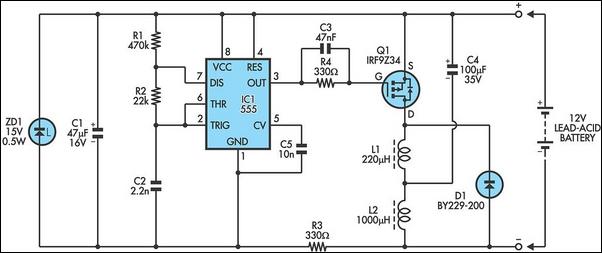
The following circuit illustrates a 6/12/24V Lead Acid Battery Charger Circuit Diagram. Features: It is essentially a high-voltage pulse generator. The circuit diagram for a 6/12/24V Lead Acid Battery Charger is designed to efficiently charge lead-acid batteries of varying voltages....
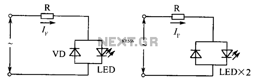
The circuit operates effectively even when the polarity of the voltage or the power supply is reversed. It functions with DC drives similar to AC drives, utilizing a current limiting resistor R. The value of this resistor is determined...
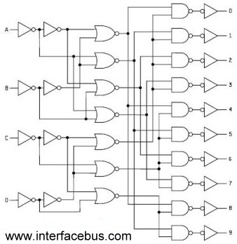
Binary Coded Decimal (BCD) is a number system that counts from 0 to 9 and then repeats. The table below illustrates the conversion between different numbering systems and BCD code. BCD is also known as 8421 because the least...
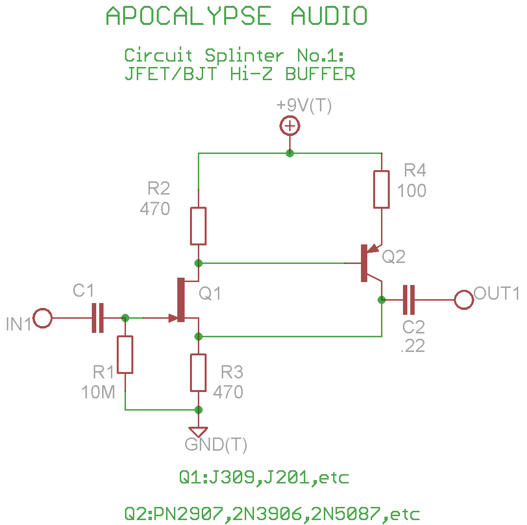
This is a common circuit often found in various resources, yet it appears to be less prevalent in stompbox applications. The circuit utilizes an NPN JFET DC coupled with a PNP BJT. The FET provides a significantly higher input...
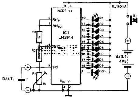
The LM3914A bar graph LED is utilized as a voltmeter for testing batteries. This circuit operates on a 4.5-V battery and compares the battery under test with an internally generated reference, established by resistors R1, R2, and potentiometer P1....