
1750M Transverter Circuit

The circuit is designed to facilitate amateur radio communication within the specified frequency band while adhering to regulatory power limits. The receiving converter is crucial for capturing signals in the lower frequency range and converting them to a more manageable frequency for processing. This allows for effective demodulation and audio output, enabling clear reception of incoming signals.
The transmitting converter is responsible for taking the signals from the 80-meter band and translating them down into the 160 to 190 kHz range. This conversion process is essential for ensuring that the transmitted signals fall within the legal operating frequency range, allowing for seamless communication without interference.
The power supply requirement of 12 to 24 V provides flexibility in the choice of power sources, accommodating both portable and stationary setups. This versatility is beneficial for amateur radio operators who may wish to operate in different environments or under varying conditions.
Overall, the circuit presents a practical solution for amateur radio enthusiasts looking to explore the lower frequency bands, providing a robust platform for experimentation and communication in the specified frequency range. This circuit was described in a recent edition of an amateur radio magazine. It allows operation in the 160- to 190-kHz band with up to 1 W (license free) in any mode (CW/SSB/FM, etc.) It consists of a receiving converter for 5 kHz to 450 kHz and a transmitting converter to convert the 3.66- to 3.69-MHz (80 meter) range to 160 to 190 kHz. A 12- to 24-V power supply can be used.
Related Circuits
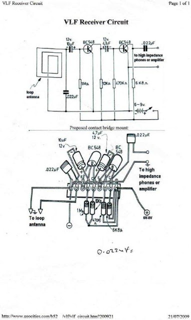
Low frequencies predominantly cover Earth's atmosphere. This range of frequencies can be produced by various unknown and unusual sources. A Very Low Frequency (VLF) sensor equipment can be developed to detect these frequencies for investigating the intriguing secrets hidden...
This article outlines the construction of a simple microcontroller-based delay circuit designed for photographic applications such as drop or high-speed photography. It can control the trigger lag of cameras and flash units, generate periodic trigger pulses, or manage magnetic...
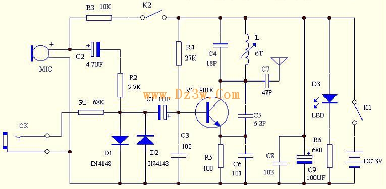
C4 and L form a resonator, where the resonant frequency corresponds to the FM transmitting power of the microphone. According to the component parameters in the diagram, the transmission frequency can range from 88 to 108 MHz. The frequency...
The integrated circuit LA3607 enables the configuration of a 7-band graphic equalizer for a single audio channel by incorporating additional capacitors and variable resistors. The cutoff frequency can be modified using variable resistors. It demonstrates high stability when handling...
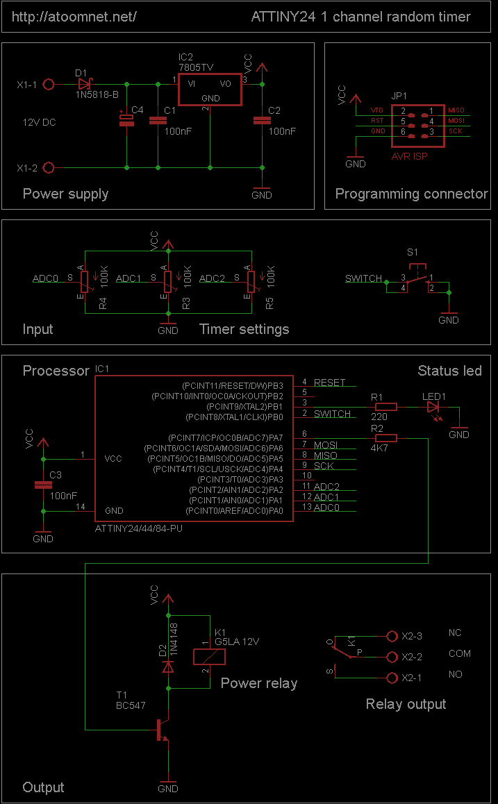
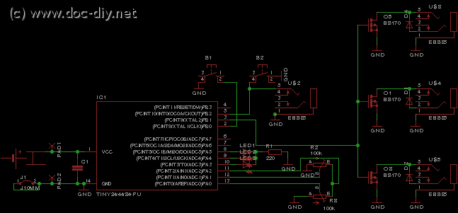
This random timer circuit is based on an Atmel ATTINY24 AVR driving one power relay. It can be used to switch on and off other circuits randomly. For instance, in a model railroad setup, this circuit can activate and...
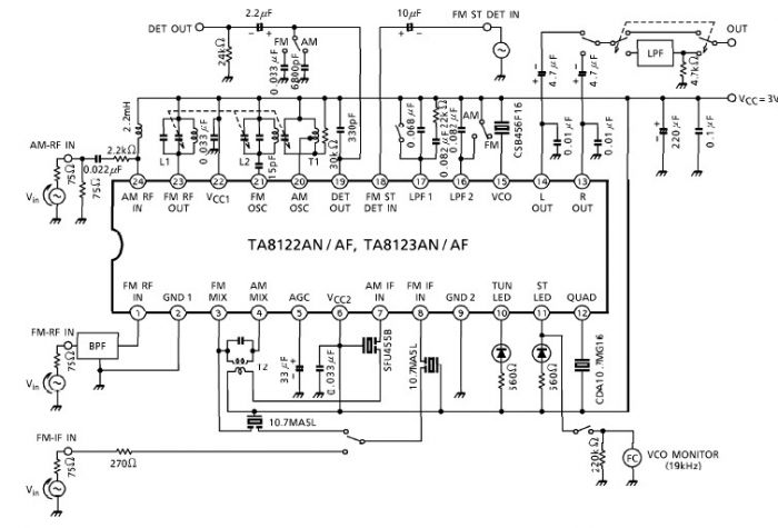
A simple low-power AM/FM radio receiver electronic project can be designed using the TA8122 integrated AM/FM receiver, manufactured by Toshiba Semiconductor. This radio receiver circuit is suitable for portable radio applications or other similar devices. The TA8122 radio receiver...