
Random timer circuit using a Attiny24A

The processor block is responsible for all calculations. The ATTINY24 reads the inputs and computes the on and off times for the random timer circuit. It contains a program with predefined random numbers generated using an online random number generator. Although these numbers are predefined, they suffice for the circuit's purpose. When duplicating the circuit with the same hex file programmed into another microcontroller, both units will initially exhibit synchronized randomness. However, due to the unstable internal RC oscillator, they will gradually drift in clock speed, appearing random over time. The output block includes a relay controlled by a transistor, with the transistor's base connected to the microcontroller. This prototype is designed as a single-channel random timer circuit, but the ATTINY24 microcontroller has five unused pins that could be configured for a six-channel random timer circuit. Some components used differ in type but maintain the same functionality; for instance, the 7805 can be replaced with an AMS1117, and the transistor driving the relay is an SMD 2N2222. A red 5mm LED is connected to the random timer circuit to indicate when the relay is activated.
The circuit employs a microcontroller programmed with an algorithm that generates random timed intervals for activating the relay. The ATTINY24's ADC (Analog-to-Digital Converter) is utilized to read the values from the potentiometers, which allow users to set specific timing parameters. The use of a relay enables the circuit to control higher power loads, making it suitable for applications beyond model railroads, such as controlling lights or motors in various electronic projects.
The design ensures that the microcontroller operates efficiently with minimal power consumption, utilizing power-saving features and interrupt-driven programming. The timer interrupt is configured to trigger every 100 milliseconds, allowing the microcontroller to manage tasks without continuous polling, thus optimizing performance. The implementation of a random number generation algorithm enhances the unpredictability of the relay activation, contributing to a more engaging experience in applications such as model railroads, where dynamic scenery is crucial for capturing the interest of viewers.
Overall, this random timer circuit offers flexibility, allowing for customization in various applications while maintaining a straightforward design that can be easily replicated or modified for different use cases.This random timer circuit is based on a Atmel ATTINY24 avr driving one power relay. You can use this circuit to switch on and off other circuits randomly. For example, when using this circuit on a model railroad you can turn on and off parts of the animated or moving scenery to create a more dynamic view. This circuit was designed to be used on a modular model railroad. This model railroad contains different flashing light on ambulances, police cars and fire engines. These lights are on all the time, with this circuit I hope to keep visitors of a model railroad exposition more interested while watching all the action. The schematic of the random timer circuit is divided into different functionality blocks. The power supply block stabilizes the 12V and protects the power input for reverse polarity. There is a standard 7805 voltage stabilizer to supply 5V to the microcontroller. The input block consists of 3 potentiometers and one button. The potentiometers can be used to configure the on and off time, and the amount of random time. ADC0 is connected the the potentiometer which configures the amount of random time between 0% and 500% extra time.
ADC1 configures the off time between 1 and 60 seconds. ADC2 configures the on time in the random timer circuit. The button is there just because I like buttons, it has no functionality. Actually, the prototype of theG‚random timer circuit I made was using one of my other boards ( the tiny dcc decoder for 8 leds ), this board already has the button, so there you go. The processor block is where all the math takes place. The ATTINY24 reads the inputs and calculates the on and off times in the random timer circuit. The ATTINY24 contains a program with predefined random number generated with my online random number generator.
These random numbers is what makes this circuit random. You might say that when it is predefined these random numbers aren`t really random, yes, but for the purpose of this circuit is works just fine. Even when duplicating this circuit and programming the same hexfile into another microcontroller they both seem random.
In the beginning they will be somewhat synchronized random, but because of the unstable internal RC oscillator they will drift over time in clock speed and then they both appear to be random. Lastly the output block contains a relay which is driven by a transistor. The transistors base (input) is connected to the microcontroller. I have chosen for this prototype to be a 1 channel random timer circuit, but the ATTINY24 microcontroller has 5 pins unused which can be combined into a 6 channel random timer circuit.
There are some parts used that are different in type, but are still have the same functionality. The 7805 is AMS1117 and the transistor that drives the relay is a SMD 2N2222 (on the bottom). You can see I connected a red 5MM led to the random timer circuit so I can see when the relay is switched on. /* * AvrStudioRandomTimer. c * * Created: 13-12-2012 21:30:06 * Author: Marc, */ #include
. high = (FUSE_SPIEN & FUSE_BODLEVEL0), //Enable Serial programming, Brown-out 1. 8V. extended = EFUSE_DEFAULT, }; #define mintime 1 #define maxtime 60 #define maxadc 65472 //Access bits like variables struct _io_reg { uint8_t b0:1; uint8_t b1:1; uint8_t b2:1; uint8_t b3:1; uint8_t b4:1; uint8_t b5:1; uint8_t b6:1; uint8_t b7:1; }; #define REGISTER_BIT(port, pin) (*(volatile struct _io_reg*)&port). b##pin) #define RELAY1 REGISTER_BIT(PORTA, 7) #define RELAY1_DDR REGISTER_BIT(DDRA, 7) #define LED REGISTER_BIT(PORTB, 1) #define LED_DDR REGISTER_BIT(DDRB, 1) #define EV100ms _BV(0) #define event GPIOR0 //This ISR runs every 100ms.
ISR(TIM0_COMPA_vect) { event |= EV100ms; } uint16_t readadc(uint8_t channel) { uint16_t adcvalue = 0; ADCSRA = 0; ADCSRA |= _BV(ADEN) | _BV(ADPS2); //ADC enable, Prescaler 16 ADMUX = channel & 0b00111111; //Discard 1st conversion. ADCSRA |= _BV(ADSC); //start conversion loop_until_bit_is_clear(ADCSRA, ADSC); //wait for end of conversion for(uint8_t i=0;i<64;i+) { ADCSRA |= _BV(ADSC); //start conversion loop_until_bit_is_clear(ADCSRA, ADSC); //wait for end of conversion adcvalue += ADC; } return adcvalue; } uint8_t GetRandomValue(uint16_t amplitude) { return (uint32_t)READrnd() * amplitude) / maxadc; } int main(void) { uint16_t timerrelay1 = 0; uint16_t onvalue; uint16_t offvalue; uint16_t onrandom = 0, offrandom = 0; uint8_t blinkcounter = 0; //Turn on power saving power_all_disable(); power_adc_enable(); //initialize 8BIT Timer0 power_timer0_enable(); TCCR0A |= _BV(WGM01); //CTC TIMSK0 |= _BV(OCIE0A); // enable timer interrupt //10Hz OCR0A = 0x61; TCCR0B |= _BV(CS00) | _BV(CS02); // CK/1024 LED_DDR = 1; RELAY1_DDR = 1; PORTB |= _BV(PB0); //Switch, pull-up //Unused pins: pull-up PORTA |= _BV(PA3) | _BV(PA4) | _BV(PA5) | _BV(PA6); PORTB |= _BV(PB2) | _BV(PB3); sei(); //enable interrupts for(;;) { while(event = 0) { //idle code } if (event & EV100ms) { event &= ~EV100ms; if (timerrelay1 = 0 ) { ADMUX &= (0b00111111); //Vcc ref; //The on and off random times are maximum 5 times the duration of the on-time.
offrandom = GetRandomValue(readadc(0) * 5; onrandom = GetRandomValue(readadc(0) * 5; } offvalue = mintime*10 + (uint32_t)readadc(1) * (maxtime-mintime)*10) / maxadc); onvalue = mintime*10 + (uint32_t)readadc(2) * (maxtime-mintime)*10) / maxadc); offvalue = offvalue + (offvalue * offrandom)/0xFF; onvalue = onvalue + (onvalue * onrandom)/0xFF; //Decrease timer if new values are lower if (RELAY1 = 0 && timerrelay1 > offvalue) timerrelay1 = offvalue; if (RELAY1 = 1 && timerrelay1 > onvalue) timerrelay1 = onvalue; if (timerrelay1 = 0 ) { //Turn on when off, off when on if (RELAY1 = 0) RELAY1 = 1; else RELAY1 = 0; //Load timing value into timer variable. if (RELAY1 = 0) timerrelay1 = offvalue; else timerrelay1 = onvalue; } timerrelay1-; //Blink the led every 1 second blinkcounter+; if (blinkcounter=10) { LED = 1; blinkcounter = 0; } else { LED = 0; } } //reset all remaining events event = 0; } }
🔗 External reference
Related Circuits
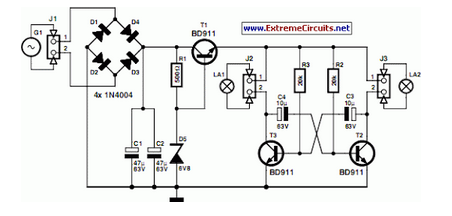
A front wheel with a built-in dynamo was purchased, providing a sine wave output of 30 Vpp at no load. Based on this, a simple power supply was designed using BD911 transistors, which are somewhat oversized for the application,...
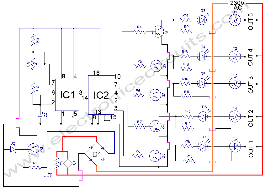
5 WAY AC FLASHER. These types of circuits are commonly used in various ceremonies such as the Wesak festival, Christmas, and weddings. This 5 WAY AC FLASHER circuit. The 5 Way AC Flasher circuit is designed to produce a sequential...
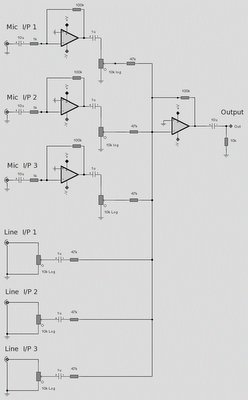
The microphone inputs are amplified approximately 100 times or 40 dB, with the total gain of the mixer, including the summing amplifier, reaching 46 dB. The microphone input is designed for microphones that produce an output of around 2...
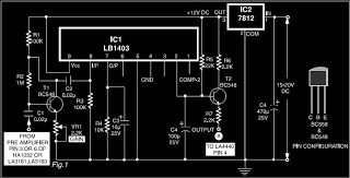
This is a circuit diagram for automatic muting in audio systems utilizing the IC LB1403. The output from a pre-amplifier, such as the LA3160, LA3161, or HA1032, is connected to the base of the amplifier transistor BC548 (T1). A...

This is an infrared-based broken beam alarm designed to protect doors and entry passages. It emits a loud alarm when someone crosses the invisible infrared barrier. The infrared-based broken beam alarm system operates by utilizing a pair of infrared emitters...
Blinks 2 LEDs in sequence. An explanation of its operation is requested. It is understood that a capacitor charges, causing the LED to turn off, and when it discharges, the LED turns on. However, clarification on the purpose of...