
175MHz high-frequency amplifier circuit composed by a field effect transistor

The 175 MHz high-frequency amplifier circuit is designed to amplify signals in the specified frequency range, making it suitable for applications in communication systems, RF signal processing, and other high-frequency applications. The core component of this circuit is the 3D04H field-effect transistor, which is known for its high gain and low noise characteristics at high frequencies.
The circuit typically consists of several key components surrounding the FET, including resistors, capacitors, and possibly inductors, which are configured to optimize the amplifier's performance. The input signal is fed into the gate of the FET, where it is amplified due to the transistor's ability to control the output current based on the input voltage.
Biasing resistors are essential for setting the operating point of the FET, ensuring that it operates in the appropriate region of its transfer characteristics for linear amplification. Coupling capacitors may be used at the input and output stages to block DC components while allowing the AC signal to pass through, thus preventing any DC biasing from affecting subsequent stages in the circuit.
Feedback components may also be included to stabilize gain and improve bandwidth. The layout of the circuit should minimize parasitic capacitances and inductances that can adversely affect high-frequency performance. Proper grounding and power supply decoupling are critical to reduce noise and ensure stable operation.
Overall, the design of this 175 MHz high-frequency amplifier circuit emphasizes the importance of component selection, layout, and biasing techniques to achieve effective amplification of high-frequency signals.175MHz high-frequency amplifier circuit by a field effect transistor shown in Fig. Field effect transistor VT is 3D04H, components, and parameters,
Related Circuits
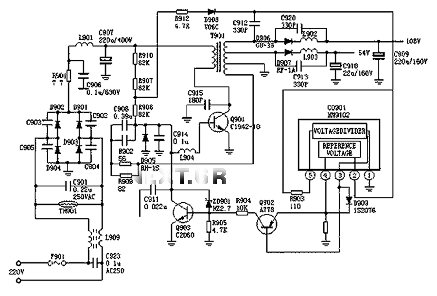
The Hitachi NP8C switching power supply circuit is illustrated in FIG. The Hitachi NP8C power models include CTP236, CEP320D, CRP350D, 450D, Furi HFC-236, 450, and Venus C37-401, C46-1, C563, among others. This circuit was widely used in early Chinese...
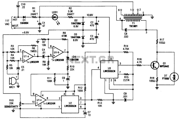
The baby-alert transmitter is constructed using an LM324 quad operational amplifier (U1), two LMC555CM CMOS oscillator/timers (U2 and U3), along with several supporting components. The transmitter activates upon detecting sound at MIC1, emitting a signal. Its operational frequency is...
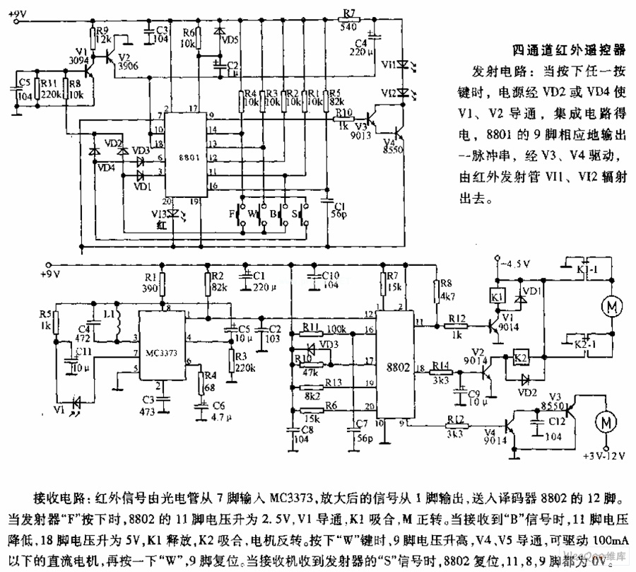
The receiving circuit involves an infrared signal being input to the MC3373 from pin 7 via a phototube. The amplified signal is output from pin 1 and sent to pin 12 of the decoder 8802. When the transmitter F...
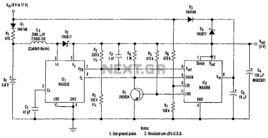
A 9-V wall adapter supplies Vm. IC2 contains a low-battery detector circuit that senses l7IN through resistors R6 and R7. The detector output at pin 7 drives an inverter (Q1), which in turn controls the shutdown inputs of IC1...
The basic two-transistor flasher has become widely utilized in various applications due to its simplicity and versatility. It has been employed in circuits such as a micropower low battery indicator, a lightning detector, an off-line switching power supply, a...
The acoustic spectrum extends from a very low frequency of 20 Hz to a high frequency of 20,000 Hz. At lower frequencies, the sense of direction diminishes. This observation leads to the recommendation of using speakers that handle very...