
Four channels infrared remote controller circuit diagram

The described receiving circuit is designed to process infrared signals through a series of components that work cohesively to control motor operations based on specific signal inputs. The circuit begins with an infrared signal captured by a phototube, which serves as the input mechanism for the MC3373. The MC3373 amplifies this signal, and the output is directed to the decoder 8802.
The decoder 8802 plays a crucial role in interpreting the signals received. The activation of the transmitter F results in a voltage increase at pin 11, which is critical for initiating motor operations. The transistor V1 is activated by this voltage, which in turn energizes relay K1, allowing the motor M to rotate forward. This forward motion indicates that the system is responsive to the transmitter's commands.
When the circuit receives the B signal, a drop in voltage at pin 11 occurs, while pin 18 sees an increase to 5V. This change in voltage levels triggers the release of K1 and engages K2, resulting in the motor reversing its direction. This feature provides the circuit with the ability to respond dynamically to different signals, enhancing its functional versatility.
The circuit also includes a function controlled by pressing W, which raises the voltage at pin 9. This action activates transistors V4 and V5, enabling the operation of low-power DC motors (under 100mA). The ability to drive these motors allows for additional functionalities, such as movement or other mechanical actions that can be controlled remotely.
The reset function is also integral to the system's operation. By pressing W a second time, pin 9 is reset, ensuring that the circuit can return to a neutral state. Furthermore, the detection of the S signal from the transmitter prompts the 8802 to reset completely, bringing both pins 8 and 9 to 0V. This comprehensive design allows for effective control of motor functions based on infrared signal inputs, showcasing the circuit's capability for remote operation and automation.The receiving circuit: the infrared signal is inputed to MC3373 from 7 foot by phototube, the amplified signal outputs from 1 foot, it is transported into the 12 foot of decoder 8802. When the transmitter F is pressed, the voltage of 8802`s 11 foot up to 2. 5V, V1 turns on, K1 pulls in, M is forward rotation. When it receives B signal, 11 foot`s vo ltage drops, 18 foot`s voltage up to 5V, K1 releases, K2 pulls in, the motor is reversal rotation. Pressing W, 9 foot`s voltage rises, V4, V5 turn on, it can drive the DC motors which under 100mA, pressing W again, 9 foot resets. When the receiver receives the transmitter`s S signal, 8802 resets, 8, 9 feet are all 0V. 🔗 External reference
Related Circuits
This circuit transmits a continuous audio tone on the FM broadcast band (88-108 MHz), which can be utilized for remote control or security applications. The circuit draws approximately 30 mA from a 6-9 volt battery and has a reception...
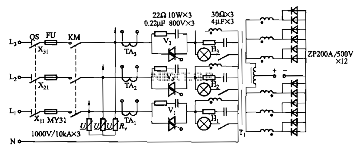
A 1500A-7V phase thyristor power regulator circuit is designed for plating applications. It consists of three major components: the main circuit, the control circuit, and the protection circuit. The control circuit includes a trigger circuit, a synchronous power supply,...
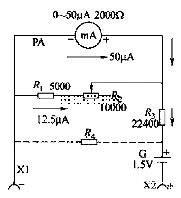
A commonly used high-sensitivity header utilizes a microammeter to create a resistance meter capable of measuring very low voltages. The design adheres to the principles of a milliameter resistance meter. The circuit diagram is illustrated in Figure 5-37, which...
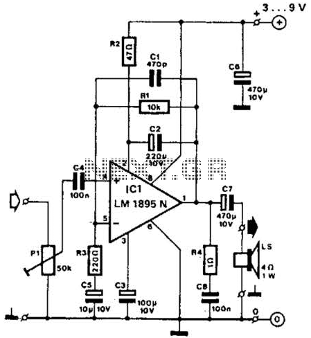
This amplifier operates with supply voltages ranging from 3 V to 9 V and can deliver an output power ranging from 100 mW to 1 W into a 4-ohm load. The bandwidth is approximately 20 kHz at a 3...
The transmitter described here includes an additional RF power amplifier stage following the oscillator stage, which increases the output power to 200-250 milliwatts. When connected to a properly matched 50-ohm ground plane antenna or a multi-element Yagi antenna, this...
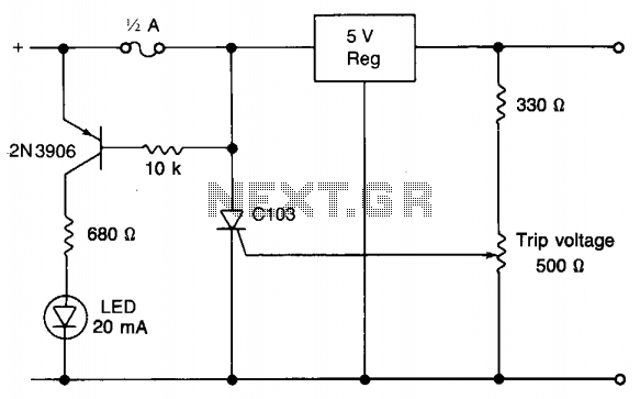
When utilizing a regulated power supply to decrease voltage, there exists a risk of component failure within the supply, potentially resulting in damage to connected equipment. While a fuse can provide protection against excessive current draw, it may not...