
1999 mercury sable: wiring diagram illumination a 3.0L vin U. I

The circuit for the clock and radio screen illumination in a 1999 Mercury Sable GS is critical for ensuring that the driver can easily read the time and radio settings, especially during nighttime driving conditions. The illumination system typically involves a series of interconnected components, including the instrument cluster, the radio unit, and the associated wiring harnesses.
In this vehicle model, the illumination for the clock and radio display is generally controlled by the vehicle's lighting circuit. When the vehicle's headlights are turned on, a voltage is supplied to the illumination circuit, which activates the backlighting for both the clock and radio display. This is often achieved through a dimmer switch that allows the driver to adjust the brightness according to their preference.
The wiring diagram will illustrate the connections between the headlight switch, the dimmer switch, and the instrument cluster. The circuit typically includes a fuse that protects against overloads, ensuring that the system operates safely. Each component in the circuit should be checked for continuity and proper connection to ensure that the illumination functions correctly.
To troubleshoot any issues with the clock and radio screen illumination, it is advisable to inspect the wiring harness for any signs of damage or corrosion, test the voltage at the dimmer switch, and verify that the bulbs within the clock and radio units are functioning. Proper diagnosis may require the use of a multimeter to measure voltage and continuity throughout the circuit.The wiring diagram for the clock and radio screen illumination for a 1999 mercury sable with a 3. 0L vin U. I have searched for hours on alldata and MichellOnDemand and have found absolutely nothing. Please help! I don`t know if it matters, but the vehicle is a mercury sable GS, not LS. I appologize for not specifying that earlier. Which one of these circuits in your diagrams would run the screen that has the clock on it Ask-a-doc Web sites: If you`ve got a quick question, you can try to get an answer from sites that say they have various specialists on hand to give quick answers. Justanswer. com. Traffic on JustAnswer rose 14 percent. and had nearly 400, 000 page views in 30 days. inquiries related to stress, high blood pressure, drinking and heart pain jumped 33 percent. Because of your expertise, you armed me with enough ammunition to win the battle with the dealer. They are installing a fuel filter and fuel pump at no charge to me. Molly USA I needed help with my car on Saturday morning. got a response in 5 minutes, and it was the perfect solution. Thanks again to your service. Jason V. Kirkland, WA I would (and have) recommend your site to others I was quite satisfied with the quality of the information received, the professional with whom I interacted, and the quick response time.
Thanks, and be sure that I`ll be back whenever I need a question answered in a hurry. Stephanie P Elm City, NC used your service this weekend with "Trecers" help. thank you, thank you, thank you. replaced an A/C fan motor. Local Auto Zone had part. $15. 00 "tracer" fee and $40. 00 for parts, I saved several hundreds of dollers at a shop. i will recommend you and use you in the future. David L. Richmond, TX 🔗 External reference
Related Circuits
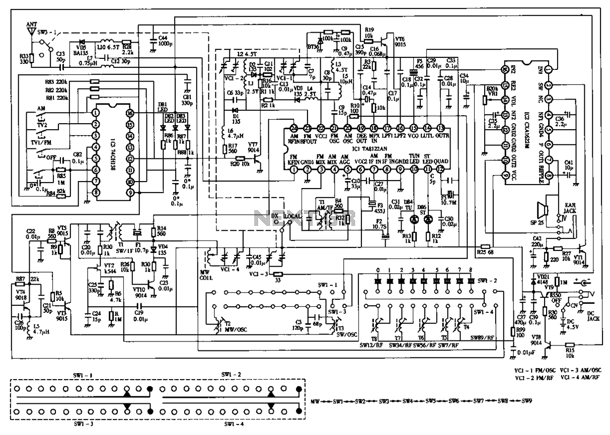
The circuit diagram for the Desheng 119 700 type FM, TV sound, medium wave, and short wave high sensitivity L2-band stereo radio is presented below. The Desheng 119 700 type radio circuit is designed to receive various frequency bands including...
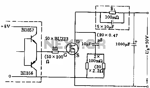
The circuit employs 50 BUZ23 field effect transistors (FETs) arranged in parallel, with a tube blocking voltage of 100V. The control power required is minimal, eliminating the risks associated with second breakdown and the positive temperature coefficient phenomenon in...

400 W MOSFET Audio Amplifier circuit using IRFP448. This circuit is categorized under amplifiers and includes five circuit diagrams. For more detailed information, refer to the main post titled "400 W MOSFET Audio Amplifier Using IRFP448." This post also...
This circuit employs an astable multivibrator to alter the state of a signal based on specific conditions. It also incorporates a flip-flop, which retains the state of the output once a change is detected, completing a cycle of the...
Wiring a three-phase motor through a two-pole vacuum switch involves two lines passing through the switch while one line remains continuously energized to the motor. Is this configuration correct, or does it present a safety concern? When wiring a three-phase...

The circuit consists of two synchronized multivibrators formed by a pair of 555 timer circuits. It is capable of generating two synchronized pulse signals, with the spacing and frequency adjustable by modifying the time constant. The circuit offers flexibility...