
Wiring A Motor Control Electrical

When wiring a three-phase motor using a two-pole vacuum switch, it is essential to ensure that the configuration adheres to safety standards and operational efficiency. A three-phase motor typically requires three separate phases (L1, L2, L3) for proper operation. In this scenario, the use of a two-pole switch means that only two of the three phases are being switched on and off, while one phase remains continuously connected to the motor.
This setup can lead to several potential issues. Firstly, if one phase is always hot, the motor may experience an imbalance in the phase supply, which can lead to overheating, increased wear, and reduced efficiency. Additionally, operating a three-phase motor with only two phases can cause it to run in an unbalanced condition, risking damage to the motor windings.
From a safety perspective, having one line always hot while the others are switched off can pose risks during maintenance or troubleshooting, as there is a potential for accidental contact with live components. It is advisable to utilize a three-pole switch designed for three-phase applications, which ensures that all phases can be disconnected simultaneously, enhancing both safety and functionality.
In summary, for optimal performance and safety, it is recommended to re-evaluate the current wiring configuration and consider implementing a three-pole switch that allows for complete disconnection of all phases, thereby ensuring that the motor operates under balanced conditions and reducing the risk of electrical hazards.I am wiring a three phase motor through a two pole vacuum switch. two lines go through the switch but one line is always hot to the motor. is this proper or is this a safety issue?.. 🔗 External reference
Related Circuits
Radio Control Circuits PDF Manual Download. This document serves as a comprehensive guide to radio control circuits, intended for individuals seeking to understand the principles and applications of radio frequency (RF) technology in controlling various devices. The manual covers fundamental...
Just point this small device at the TV and the remote gets jammed. The circuit is self-explanatory. 555 is wired as an astable multivibrator for a frequency of nearly 38 kHz. This is the frequency at which most of...
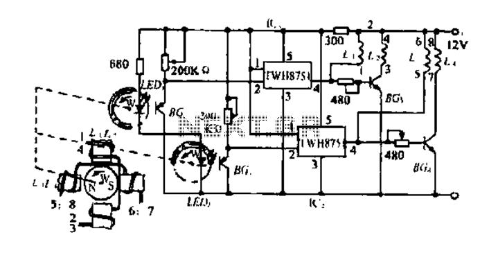
To activate a water magnet, the stator coil is divided into four groups. Each set of coils is controlled by pulse signals generated by the rotor, creating a rotating magnetic field. This operation is facilitated by controlling the signals...
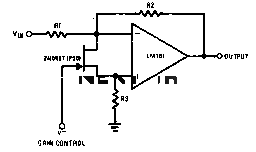
The 2N5457 functions as a voltage-variable resistor with a maximum RdS of 800 ohms. Given that the differential voltage on the LM101 is in the low millivolt range, the 2N5457 JFET exhibits linear resistance over several decades, offering excellent...

The Dodge Aspen was a compact car produced from 1976 to 1980 by Chrysler Corporation's Dodge division. The 1976 Aspen model year was available as a 2-door coupe, 4-door sedan, or 4-door station wagon, and it came in three...
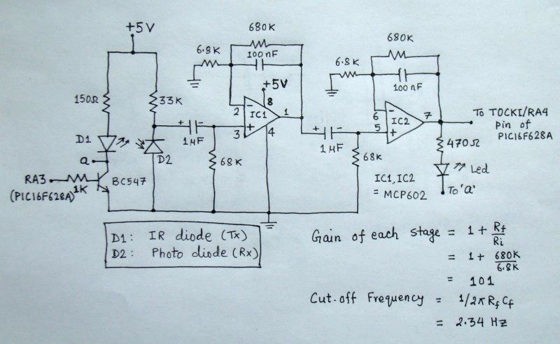
The reflected infrared (IR) signal detected by the photodiode is sent to a signal conditioning circuit, which filters out unwanted signals and amplifies the desired output. The circuit begins with a photodiode that captures the reflected IR signals. The photodiode...