
1Hz Timebase For Readout And Counter Applications

The described counter circuit is an effective tool for frequency measurement and signal processing applications. It utilizes a combination of digital logic gates, specifically XOR gates, to manipulate clock pulses and generate the necessary timing signals for latching and resetting operations. The 1-Hz time base serves as a reliable reference frequency, ensuring accurate counting and timing.
The design's flexibility to select polarity is advantageous in various applications, allowing the user to adapt the circuit to different signal requirements. The differentiation and inversion processes performed by U2A and U2B are critical for generating precise pulse widths, which are essential for reliable latching. The 200-µs and 50-µs pulse widths are tailored for optimal performance in the context of frequency measurement.
The additional delay introduced by U2C ensures that the reset pulse does not interfere with the latching operation, maintaining the integrity of the counting process. The ability to control the output pulse polarity through U2C's input is a significant feature, providing further versatility in output signal characteristics.
Overall, this counter circuit exemplifies a robust design for frequency measurement, integrating essential digital logic components to achieve accurate and flexible operation. It is suitable for applications ranging from laboratory frequency analysis to embedded systems requiring precise timing control. This counter makes direct readout of frequency-generating equipment very easy when a 1-H z time-base is added to latch, reset, and the count signal is conditioned. This design has the flexibility to select either polarity. By differentiating, inverting, and ORing the clock pulses in XOR gate U2A, a stream of 1-Hz, positive, 200-/as pulses is generated. For latching, the 1-Hz stream is again differentiated in U2B, input 1 to supply a 50-/as pulse. Though U2B"s output goes from high to low, it can be reversed, by making input 2 low. Because the reset pulse must occur after the latch signal, the 1-Hz stream from U2A is delayed 100 at U2C input 1.
The output-pulse polarity is determined by making U2C"s input 2 either high or low.
Related Circuits
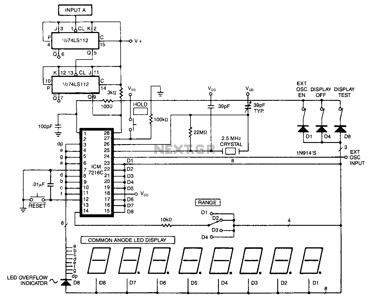
The Digi-Tach includes a master clock circuit (U6), latch and reset pulse generators (U2-b to U2-d), an input signal conditioner (U1, U2-a), a pulse counter (U3), display components and drivers (DIS1, DIS2, U4, and U5), as well as a...
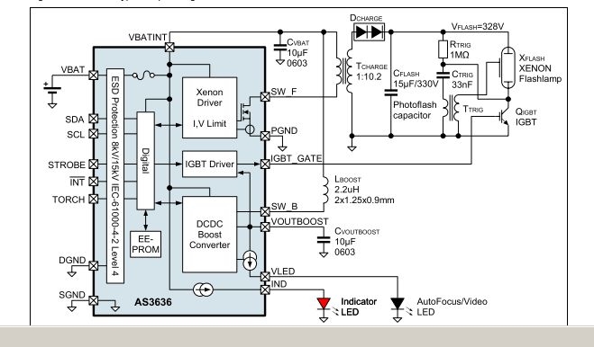
The AS3636 is a highly integrated photoflash charger that includes an IGBT driver, an inductive DC-DC boost autofocus/video LED driver, an indicator LED driver, and incorporates system-level ESD protection. The AS3636 is designed for efficient photoflash charging applications, providing a...
This circuit is capable of measuring frequencies up to 40 MHz. To achieve accurate measurements, it is essential to divide both the oscillator frequency and the input frequency by four. Consequently, the time interval between measurements is extended to...
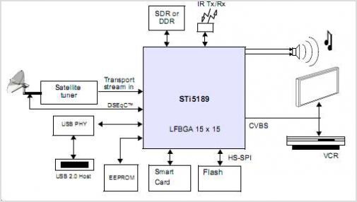
The STI5211 is a standard definition, full back-end processor designed for satellite set-top boxes, adhering to ATSC, SMPTE VC-1, DVB-S2, DIRECTV, DCII, and ARIB BS4 specifications. It delivers high performance for low-cost standard definition systems. Compared to the STi5202,...
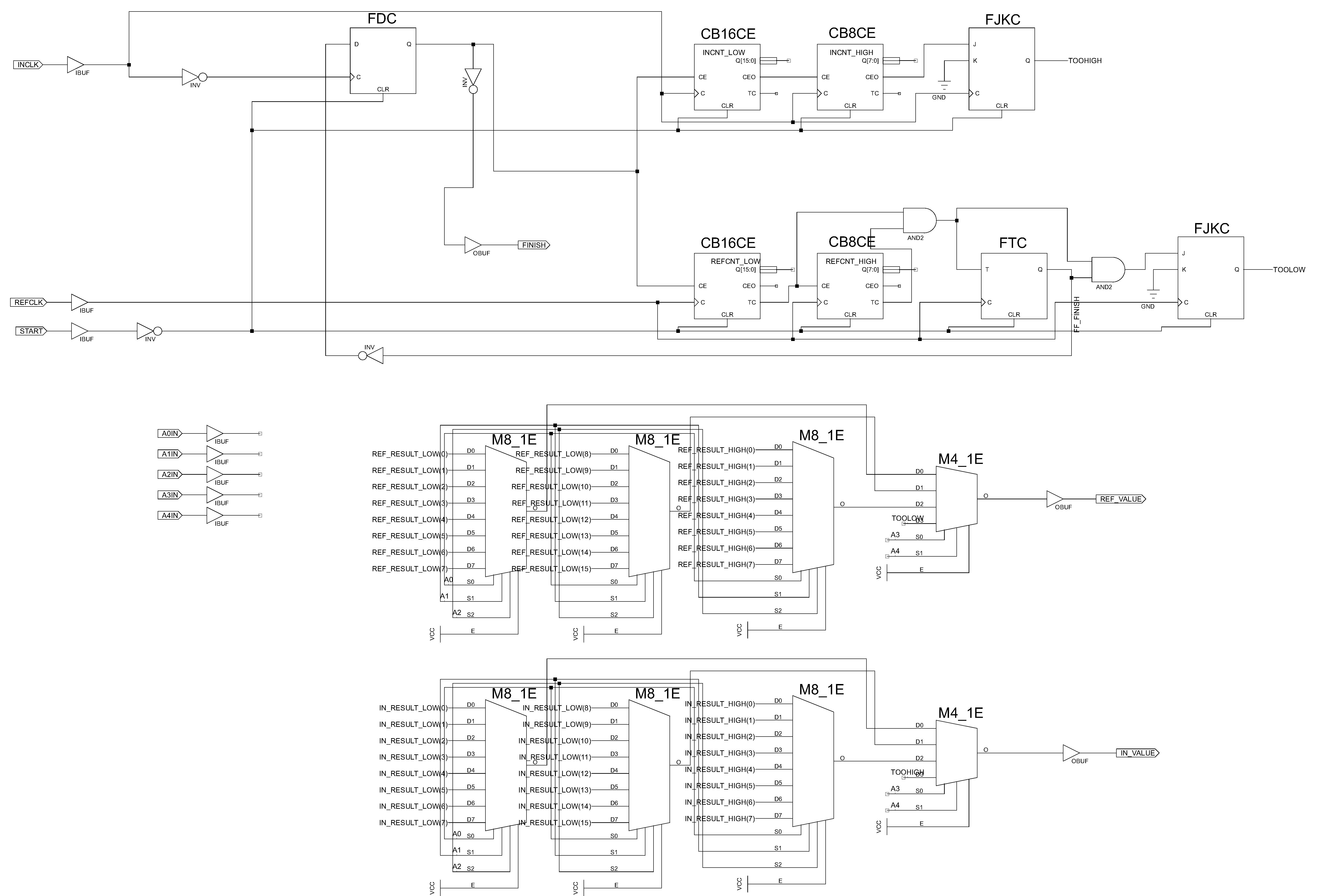
Connecting the CPLD board to a ChipKit board to enable the reading of the measured frequency. The connection between a Complex Programmable Logic Device (CPLD) board and a ChipKit board is essential for applications that require frequency measurement. The CPLD...
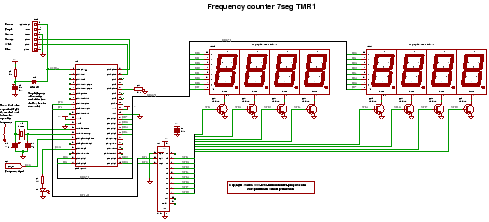
C code for a frequency counter circuit operating up to approximately 50 MHz, utilizing a multiplexed seven-segment display and employing Timer 1 to count the edges of the input signal. The frequency counter circuit described operates effectively within the range...