
frequency counter circuit

The frequency counter circuit described operates effectively within the range of up to 50 MHz. It utilizes a microcontroller that is programmed with C code to manage the counting of signal edges, which is crucial for accurately determining the frequency of the input signal. The circuit incorporates a multiplexed seven-segment display to visually represent the counted frequency, allowing for easy reading and interpretation of the data.
The core of the circuit relies on Timer 1 of the microcontroller, configured to operate in a mode that allows it to count the rising or falling edges of the input signal. This configuration is essential for capturing the frequency accurately. The microcontroller is programmed to increment a counter each time an edge is detected, with the count being displayed on the multiplexed seven-segment display.
The multiplexing of the display is achieved by rapidly switching between the segments of each digit, which creates the illusion of a steady display. This method is efficient and allows for the use of fewer pins on the microcontroller while still providing a clear output. The C code handles the timing of the multiplexing and ensures that the display is updated in synchronization with the counting process.
In summary, the frequency counter circuit integrates a microcontroller, Timer 1 for edge detection, and a multiplexed seven-segment display to provide an accurate and user-friendly method for measuring frequencies up to 50 MHz. The design and implementation of this circuit highlight the importance of precise timing and effective display management in electronic frequency measurement applications.and C code for a frequency counter circuit operating up to about 50MHz using a multiplexed seven segment display and uses timer 1 to count edges of the input signal.. 🔗 External reference
Related Circuits
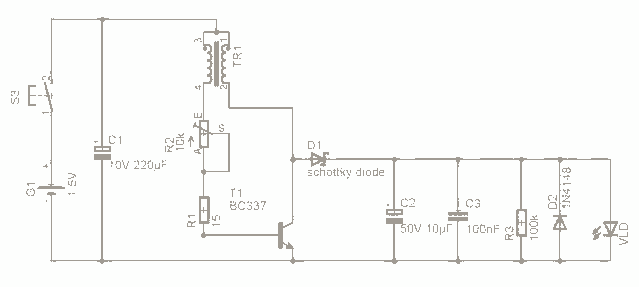
For the past few days, research has been conducted on an intriguing boost circuit known as the Joule Thief. The original schematic can be found through online resources. The Joule Thief is a simple yet effective boost converter circuit designed...
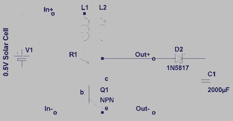
A steam engine-powered carousel project that utilizes the Joule Thief circuit. This project combines the classic charm of a steam engine with the innovative Joule Thief circuit, creating a unique carousel that operates efficiently. The steam engine serves as the...
The schematic for an infrared burglar alarm circuit is depicted in Figure 1. The infrared transmitter operates as a multivibrator with an oscillation frequency of 40 kHz, utilizing the NE555 integrated circuit (IC2), along with resistors R1 and R2...

The LED meter circuit is more compact and simpler than its analog equivalent, making it a common choice in audio equipment. This circuit utilizes the LM3915 integrated circuit (IC) and operates in a logarithmic mode. It comprises a single...
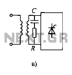
Diodes and thyristors have limited tolerance to over-current and over-voltage conditions. Short-term exposure to excessive voltage or current can damage these components and prevent them from achieving their full potential. The parameters of these devices should be determined based...
Digital visitor counter is a reliable circuit that takes over the task of counting Number of Persons/ Visitors in the Room very Accurately. When somebody enters into the Room then the Counter is Incremented by one and when any...