
Implementing the frequency counter

The connection between a Complex Programmable Logic Device (CPLD) board and a ChipKit board is essential for applications that require frequency measurement. The CPLD serves as a versatile logic component that can implement various digital functions, while the ChipKit board provides a microcontroller platform for executing higher-level tasks, including data processing and communication.
To establish this connection, it is crucial to identify the appropriate pins on both boards. The CPLD board typically has dedicated input pins that can be configured to read digital signals corresponding to the measured frequency. These input pins should be connected to the output pins of the ChipKit board, which may be configured to generate a square wave signal representing the frequency of interest.
The connection can be made using jumper wires or a ribbon cable, ensuring that the signal integrity is maintained. It is also advisable to include pull-up or pull-down resistors on the CPLD input pins to stabilize the signal levels and prevent floating inputs, which can lead to erroneous readings.
Once the physical connection is established, the CPLD must be programmed to interpret the incoming frequency signal. This typically involves writing a hardware description language (HDL) code that defines the behavior of the CPLD in terms of counting pulses or measuring the time period of the incoming signal. The ChipKit board, on the other hand, should be programmed to handle the data received from the CPLD, which may involve serial communication protocols such as UART or SPI for transmitting the frequency data to a host computer or other peripherals.
In summary, the integration of a CPLD board with a ChipKit board for frequency measurement involves careful planning of the connections, appropriate signal conditioning, and programming both devices to ensure accurate and reliable data acquisition.Connecting the CPLD board to a ChipKit board, to be able to read the measured frequency. 🔗 External reference
Related Circuits
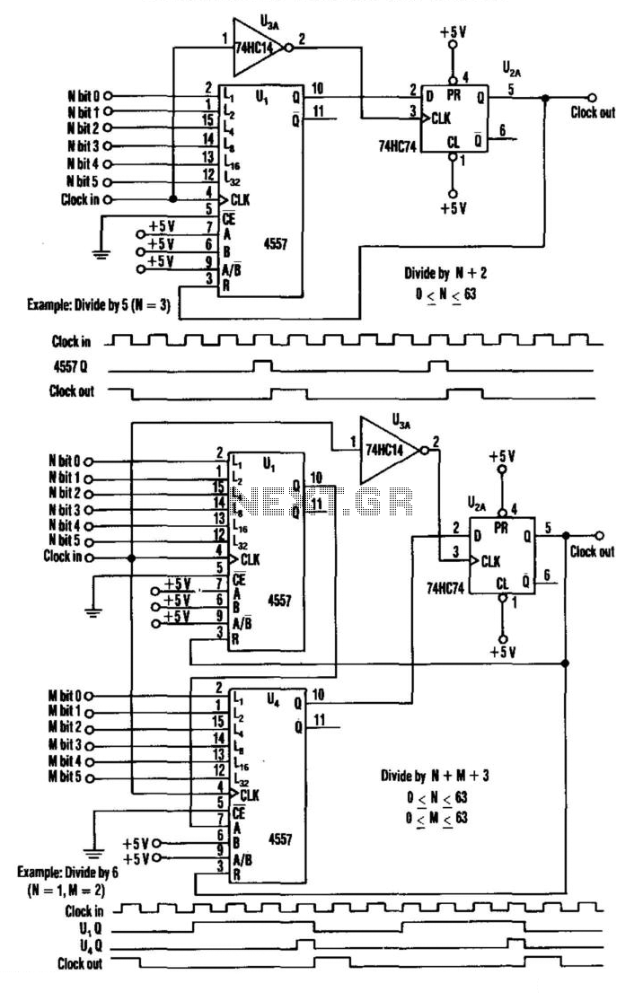
This divider utilizes a variable-length shift register, a type-D flip-flop, and an inverter. The clock signal is connected to the clock input of the flip-flop, while the output of the shift register is connected to the D input of...
Programming of the PIC microcontroller is required prior to its utilization in this circuit, which necessitates the use of a programmer. A suitable programmer can be located by searching for "Multi-PIC Programmer." The PIC microcontroller serves as the core component...
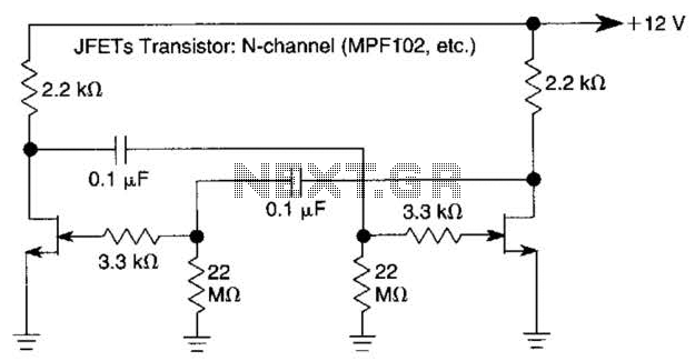
The use of JFETs allows for high resistance and long time constants in this very low frequency multivibrator. The values indicated are for operation at 0.15 Hz. In the context of electronic circuit design, a multivibrator is a circuit that...
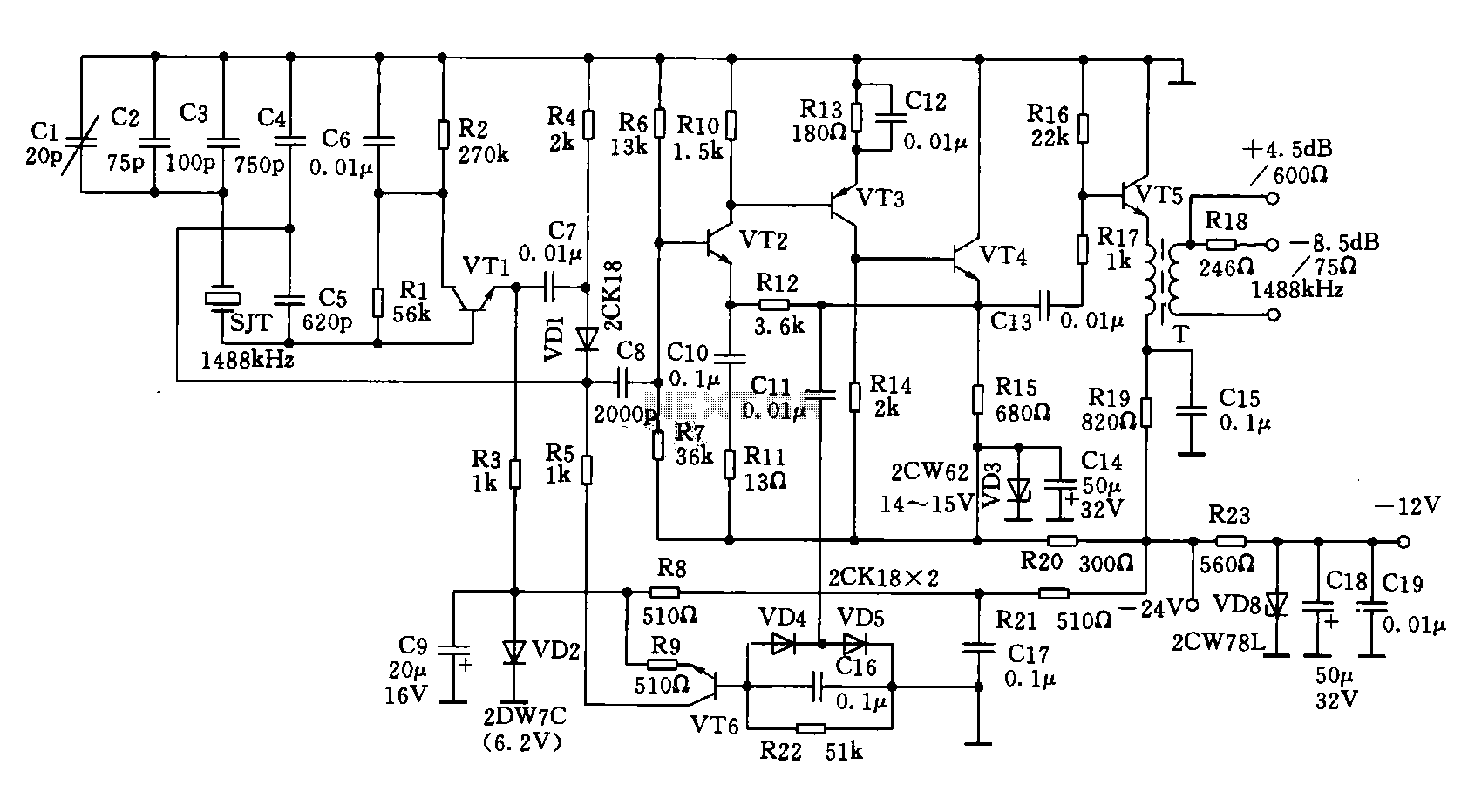
A 1488 kHz master oscillator quartz crystal resonator is utilized for frequency stabilization. The output from the frequency divider provides three different square wave signal outputs at 4 kHz, 12 kHz, and 124 kHz. The circuit includes transistors VT1,...
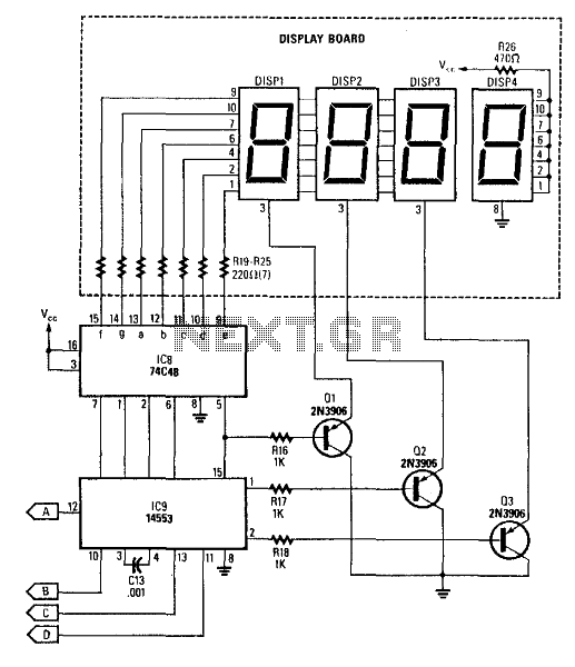
This circuit produces a readout for the digital tachometer circuit. IC9 is a 3-digit LED display driver, counter, and latch. IC8 drives the common-cathode LEDs, which are enabled by Q1, Q2, and Q3. See page 268, Fig. 46-5 for...
These parameters are expected with an approximately 50% square wave up to frequencies of several MHz, and symmetric sine waves at higher frequencies. The primary limitation is based on the maximum clocking rate specification for the MM74HC6040 ripple counter...