
1MHz quartz crystal oscillator circuit

The described oscillator circuit operates at a frequency of 1MHz, leveraging the properties of a quartz crystal resonator to achieve stable oscillations. The quartz crystal functions as a frequency-selective component, providing precise frequency control due to its inherent mechanical resonance characteristics. When integrated into the circuit, the crystal ensures that the oscillation frequency remains consistent and reliable, which is crucial for applications requiring accurate timing signals.
The NAND gate configuration is employed to create a feedback loop necessary for sustaining oscillations. In this setup, the output from the NAND gates is fed back into the circuit, allowing for continuous oscillation generation. The use of NAND gates is advantageous due to their versatility and the ability to implement various logic functions within the same circuit.
NAND gate 3 serves as the output buffer stage, providing a clean and robust signal that can drive other components or circuits without significant loading effects. This buffering is essential to maintain signal integrity, particularly when the generated frequency signal is interfaced with other electronic systems.
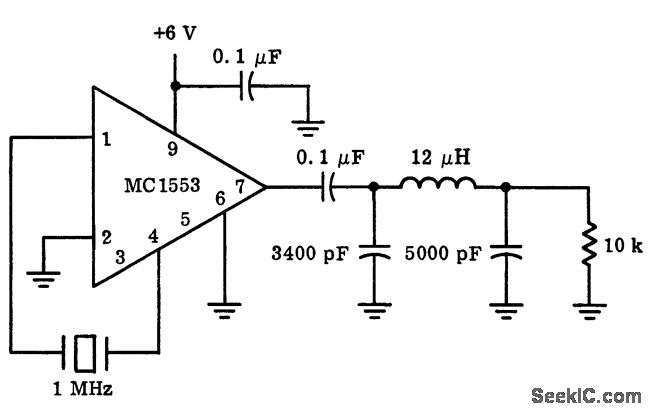
In practical applications, this 1MHz quartz crystal oscillator circuit can be utilized in various fields such as telecommunications, signal processing, and frequency calibration for precision instruments. The design's simplicity and effectiveness make it an ideal choice for generating stable clock signals in digital circuits and microcontroller applications.The oscillator circuit which is composed of the 1MHz quartz crystal resonator and the NAND gate is as shown in the figure, the NAND gate 3 is the output buffer stage. This circuit can be used to calibrate the standard frequency. Figure 1 The 1MHz quartz crystal oscillator circuit.. 🔗 External reference
Related Circuits
There are neighbors who may disturb you with loud televisions or radios. A solution is available. This jammer emits jamming waves that affect the TVs and radios in the neighborhood, so caution is advised. This device is an enhanced...
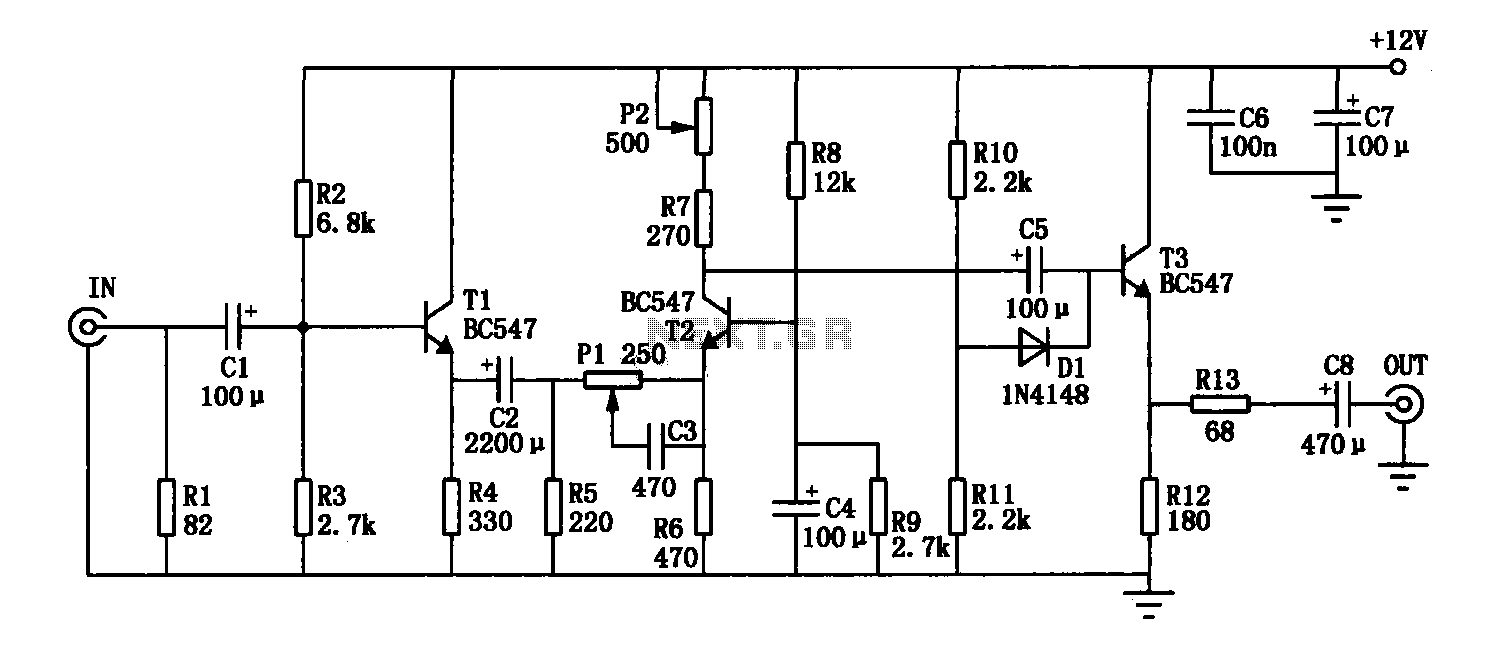
The enhancement circuit, as depicted, increases the high-frequency components of the video signal, thereby improving the contrast of the television image. It can be connected between the VCR and the TV SCART input. The circuit utilizes transistor T1 for...
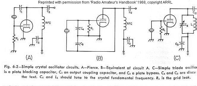
The frequency of a crystal-controlled oscillator is maintained with high precision through the use of a quartz crystal. The frequency is primarily determined by the dimensions of the crystal, particularly its thickness, while other circuit parameters have minimal impact....
More: The provided input lacks specific details or context regarding an electronic circuit or schematic. To create a comprehensive electronic schematic description, it is essential to include key components, their interconnections, and the overall functionality of the...
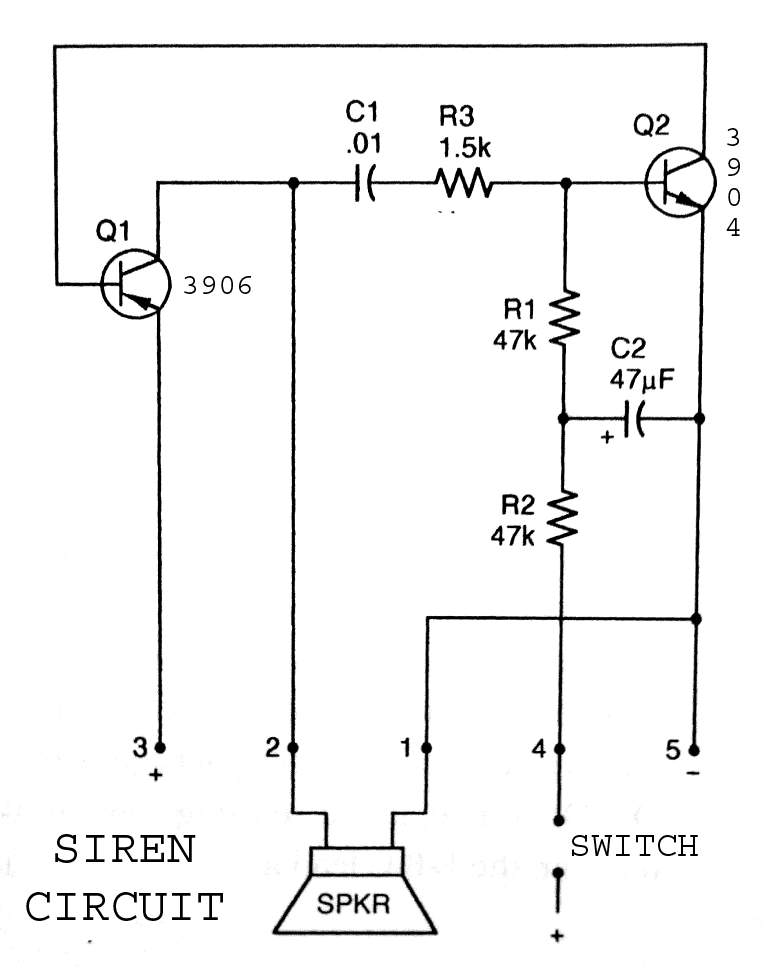
3904 3906 Siren Circuit. The circuit generates a wailing siren sound when the switch is activated. The 3904 3906 Siren Circuit is designed to produce a distinctive wailing sound, commonly used in alarm systems and signaling devices. The circuit utilizes...
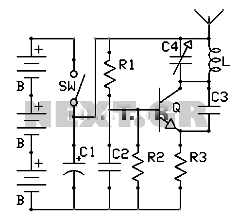
A schematic diagram of the oscillator is presented in Figure 1. The common-base transistor stage (Q1) amplifies the signal within the positive feedback loop. The positive feedback signal develops across the resistor R1, which is shared by the emitters...