
Video enhancement circuit diagram

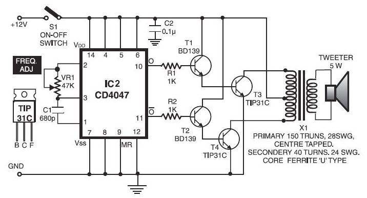
The enhancement circuit is designed to improve the quality of video signals by amplifying high-frequency components, which are crucial for image clarity and contrast. The circuit operates by connecting the output between a VCR and a television's SCART input, facilitating seamless integration into existing setups. The use of transistor T1 serves to dampen unwanted signals, ensuring that only the desired frequencies are amplified.
Resistor R1 is critical in maintaining an input impedance of approximately 75 ohms, which is standard for video signals, allowing for optimal signal transfer and minimizing reflections. The amplifier stage, represented by transistor T2, is where the main signal amplification occurs. The gain of this stage is adjustable through potentiometer P2, which provides flexibility for varying input signal strengths. The frequency response of T2 is shaped by the interaction of components P1, R6, and C6, allowing users to tailor the circuit's performance to their specific needs.
Transistor T3 functions as a buffer, ensuring that the circuit can drive a standard 75-ohm load effectively. This is important for maintaining signal integrity when interfacing with other equipment. The output level can be fine-tuned using potentiometer P2, allowing for an output of 1 Vp-p, with the expectation that the open-circuit output will reach 2 Vp-p. This design not only enhances the visual quality of the television image but also provides users with the ability to customize their viewing experience.Enhancement circuit as shown in the high-frequency component of the video signal can be increased, thereby enhancing the contrast of the TV image, it can also be connected to t he output terminal between the VCR and the TV SCART input. Circuit transistor Tl dampening effect. The resistance Rl ensure enhanced input impedance of the circuit is approximately 75. Signal applied to the amplifier stage T2, the gain depends on the position of the potentiometer P2. T2 signal frequency characteristics of the base by Pl, R6, C6 constraints, and therefore to some extent, controllable by the user (via Pl). T3 buffer stage provides sufficient current for properly driving the vast majority 75 load. Adjust the potentiometer P2, the output is 1Vp-p (open-circuit output level should be 2Vp-p).
Related Circuits
This circuit is very simple, which minimizes the likelihood of issues. It can be installed anywhere on the phone line and will record any conversation occurring on that line. It should be noted that there have been several reports...
The foot 13 between valve value 1 and valve value 2 will draw the transistor base current. If the relay releases, after a recovery time of 0.5 seconds, pressing the key will initiate the switching process again. The timer...
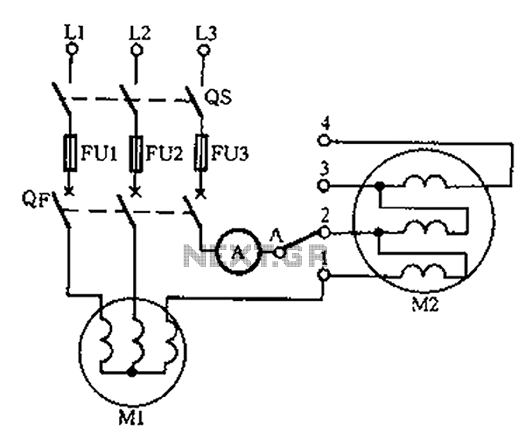
Below is a circuit diagram for detecting motor winding current imbalance during the drying process. The circuit diagram is designed to monitor the current flowing through the windings of a motor used in drying applications. This imbalance detection is crucial for...
This digital thermometer circuit diagram utilizes a standard 1N4148 diode as the temperature sensor. The temperature coefficient of the diode is -2 mV/°C. The digital thermometer circuit leverages the characteristics of the 1N4148 diode, which exhibits a predictable voltage drop...
The electronic dog repellent circuit diagram below is a high-output ultrasonic transmitter primarily intended to act as a dog and cat repeller. The electronic dog repellent circuit utilizes a high-frequency ultrasonic transmitter to emit sound waves that are unpleasant to...
The circuit of the unit is relatively straightforward; however, setting it up can be somewhat challenging. The difficulty arises from the need for matched FETs, which are not easily obtainable. Therefore, it was essential to ensure that the circuit...