
High Power Portable TV and FM Jammer circuit

The power source consists of three 9-volt batteries connected in series, providing a total input of 27 volts, which results in a powerful output of 2.5 watts. A simple wire antenna measuring between 70 cm and 2 meters is necessary for operation. The transistor used in this circuit is the 2N3553, a radio frequency power silicon NPN transistor housed in a TO39 package, designed for use in amplifiers and oscillator applications in military and industrial settings. Typically utilized as an output driver or in pre-driver stages within VHF equipment, this application prioritizes power over modulation, justifying its use as both the initial and final output driver.
The transistor operates at a frequency of 175 MHz and a voltage of 28V, providing an output power of 2.5 watts, a minimum gain of 10 dB, and an efficiency of 50%. The components required for this circuit include: R1=10k, R2=2.2k, R3=100, C1=47uF/50V, C2=2.2nF, C3=10pF, SW=switch, and B=9V battery. The coil L should consist of approximately five closely wound turns, starting with a distance of 1.5 mm between turns, utilizing enameled copper wire with a 1 cm internal diameter and leads measuring 2x20 mm. The variable capacitor C4 should be an air trimmer capacitor rated between 4 to 30 pF or the closest available value.
Batteries should be connected in series, and a suitable heat sink for the TO39 case must be installed. Finally, all components should be housed within a compact plastic enclosure for optimal performance.There are still neighbors that keep annoying you by having loud the TV or the radio? Well I have you the solution. In fact all neighborhood will face your jamming waves at their TVs and radios, so be careful. This Jammer is the improved version of the old "TV and FM jammer schematic" with the difference of much higher power. Many of you where asking for a stronger and wider effect but to be as portable as can be. Looking at the schematic you can see that, only the parts are changing keeping the basic circuit intact.
Have in mind that this version needs heat sink and antenna to keep the transistor alive.
Related Circuits

The following circuit illustrates the connection of the Devantech SRF04 Ultrasonic Sensor to the SV203 powered PPRK Circuit Diagram. This circuit is based on the Devantech SRF04 sensor and features a minimum initiation time of 10 milliseconds for the...

This remarkably straightforward circuit enables the operation of one or two robust 12V 21W car bulbs in a flashing mode using a power MOSFET. Such devices are especially suitable for road, traffic, and yard alerts, as well as in...
This project utilizes an LM338 adjustable three-terminal regulator to deliver a current of up to 5A with a variable output voltage ranging from 2V to 25V DC. It is particularly useful for powering various electronic circuits during the assembly...

TMP01 is a temperature sensor that features a programmable temperature controller, an integrated reference voltage source, a current source, a voltage comparator, and an amplifier circuit. The internal circuit function block diagram and basic application circuit are provided. The key...
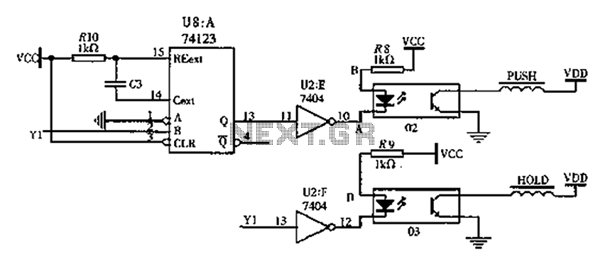
The FIG switching solenoid driver circuit utilizes the 74123 device chip (U8) and solid-state relays (02, 03). The switching electromagnet coil is referred to as the PUSH coil, while the HOL is maintained at a power supply voltage (VDD)...

This battery saver circuit can automatically turn off a small piece of test equipment after a desired period of time, allowing for worry-free operation in a workshop environment. The circuit utilizes a CD4011 integrated circuit (IC) to function as...