
1W Stereo Headphone Amplifier based TDA2822 circuit diagram

The TDA2822 is a dual audio power amplifier IC capable of delivering up to 1W of output power per channel. This makes it suitable for driving headphones in portable applications. The circuit typically consists of the TDA2822 IC, passive components such as resistors and capacitors, and may also include additional features like volume control and power supply regulation.
In a standard configuration, the TDA2822 is connected with its input pins receiving audio signals from a source device, such as a smartphone or portable media player. The output pins are connected to the headphone load. The amplifier circuit may also incorporate a coupling capacitor at the input to block any DC offset from the audio source, ensuring that only AC signals are amplified.
Power supply considerations are crucial for the performance of the amplifier. The TDA2822 operates effectively with a supply voltage range, typically from 3V to 15V, allowing for flexibility in battery-powered applications. A decoupling capacitor is often placed close to the power supply pins of the IC to stabilize the voltage and minimize noise.
To enhance user experience, a potentiometer can be integrated into the circuit to provide adjustable volume control, allowing the user to set the desired listening level. Additionally, the circuit layout should ensure proper grounding and minimize interference from other components to maintain sound quality.
Overall, the 1W stereo headphone amplifier circuit based on the TDA2822 offers an efficient and compact solution for audio amplification in portable electronic devices, making it a popular choice among engineers and hobbyists alike.1W stereo headphone amplifier circuit, built based TDA2822, designed portable players, radios and other electronic devices which can use headphone as the output. 🔗 External reference
Related Circuits
The following circuit presents a Mini Audio Amplifier Circuit Schematic Diagram. Features include a power consumption of less than 3mA, a small output, and the use of a push-pull configuration. The Mini Audio Amplifier Circuit is designed to amplify low-level...
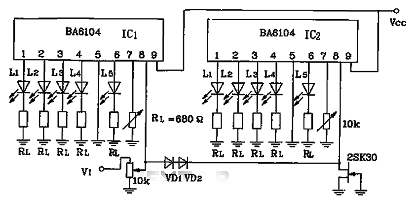
BA6104 is a five-digit LED level meter that functions as an LED display driver integrated circuit (IC). The configuration of the circuit is illustrated in the accompanying figure. The circuit utilizes a 10 by two-dot LED level display. The...
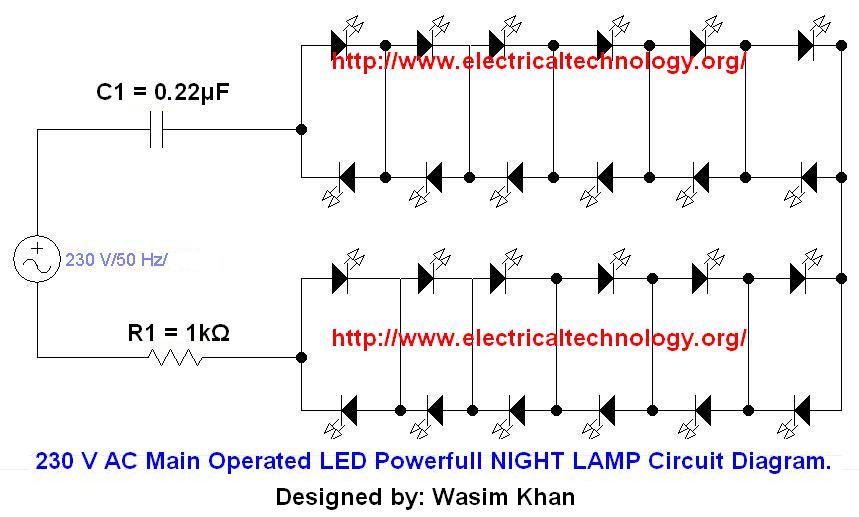
If you plan to use this circuit with a 110V 60Hz supply instead of a 230V 50Hz supply, or if you intend to modify this circuit, please refer to the section titled "Common Questions about this Circuit" found below...
This article presents basic circuits for pulsing infrared LEDs and low-power visible semiconductor lasers utilizing inexpensive and readily available components. Numerous interesting and practical applications are referenced, alongside several online resources. The focus of the article is on the...
The primary goal of this project is to utilize 555 timers to detect motion in the surrounding environment. The output of this circuit will activate an LED and produce an audible sound similar to an alarm. The circuit design employs...
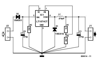
This 3-volt car adapter circuit is based on a standard LT1074CT switching regulator IC. The schematic shows the LT1074CT used as a positive step-down regulator. The 3-volt car adapter circuit employs the LT1074CT, which is a high-efficiency switching regulator capable...